
Related Manuals for Posch SmartCut 700

Summary of Contents for Posch SmartCut 700
- Page 1 Operating Instructions SmartCut 700 D1010521 - V001 *D1010521-V001* English Copyright by Posch Gesellschaft m.b.H., Made in Austria...
- Page 2 Machine number:................Serial number:..................POSCH Austria: 8430 Leibnitz, Paul-Anton-Keller-Strasse 40, telephone: +43 (0) 3452/82954, fax: +43 (0) 3452/82954-53, e-mail: leibnitz@posch.com POSCH Germany: 84149 Velden/Vils, Preysingallee 19, telephone: +49 (0) 8742/2081, fax: +49 (0) 8742/2083, e-mail: velden@posch.com...
-
Page 3: Table Of Contents
Contents Contents Foreword Copyright notice Liability for defects Reservations Definitions Operating instructions Safety information Explanation of symbols General safety information Noise Remaining risks Proper use Incorrect use General Scope Description Major machine components Stickers and their meaning Set-up Start-up Electric motor drive Driven by tractor via universal joint shaft Electric motor or universal joint shaft drives Operation... - Page 4 Contents Protective guards Screw fittings Electrical equipment Hydraulic lines Saw blade V-belt tension Oil level Maintenance Lubrication Saw blade Changing the V-belt Oil changing Conveyor belt Cleaning Special equipment 10.1 Log stop continuous Additional equipment 11.1 Hour meter (PTO drive) Troubleshooting 12.1 Disposal...
-
Page 5: Foreword
Foreword Foreword Thank you for buying our product. This machine has been built in conformity with applicable European standards and regulations. These operating instructions explain how to operate the machine safely and efficiently and how to maintain it. Any person entrusted with the transport, installation, commissioning, operation or maintenance of the machine must have read and understood: ▪... -
Page 6: Operating Instructions
Foreword The operating personnel (operators) are those entrusted by the operator to operate the machine. Technical personnel Technical personnel are persons entrusted by the operator of the machine with special tasks such as installation, set-up, maintenance and troubleshooting. Electrician An electrician is a person who, by virtue of his specialist training, has knowledge of electrical systems, standards and regulations and is able to identify and prevent possible hazards. -
Page 7: Safety Information
Safety information Safety information Explanation of symbols The following symbols and instructions in this manual provide warnings about possible personal injury or property damage or give useful information about working with the machine. Warning about danger zones Instruction regarding safe working, where non-compliance entails the risk of serious or fatal injury. -
Page 8: General Safety Information
Safety information Wear safety shoes Instruction Symbol for proper use of the machine. Non-compliance can result in malfunctions or damage to the machine. Further information Symbol for further information relating to a bought-in part. Information Action-related information. General safety information The machine may only be operated by persons who are familiar with the machine’s operation and hazards and with the user manual. - Page 9 Safety information Switch off the machine's drive unit before carrying out any adjustments. Only use original - POSCH - spare parts. Do not modify or tamper with the machine. Work on electrical equipment must only be carried out by qualified electricians.
-
Page 10: Noise
It is up to the operating personnel to ensure that work is carried out safely. Proper use The machine - SmartCut 700 - is designed exclusively for sawing logs with a diameter of 7-20 cm and a length of 15-120 cm. -
Page 11: Incorrect Use
Safety information Incorrect use Any incorrect use or use other than that specified under "Proper use" is expressly forbidden. -
Page 12: General
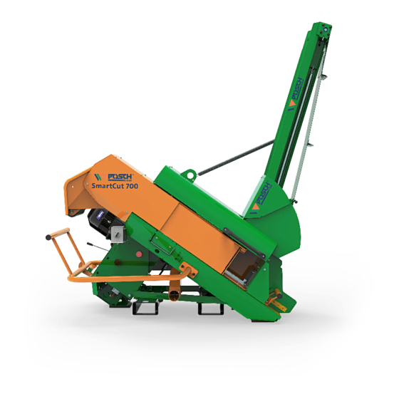
Hour counter for machines with Z motor Description The SmartCut 700 machine is a high-power saw with a fitted conveyor belt. The machine is driven by an electric motor or a pto. The log carriage is stopped by activating the switch bracket (EasyStop). -
Page 13: Major Machine Components
General Major machine components Switch Frame Log carriage Three-point linkage connection Rope winch - conveyor belt Drive – PTO shaft Protective cover Rating plate Log stop Plug with master switch Lifting eye Control levers - operation Saw blade Guard bar Conveyor belt Electric motor Cover –... -
Page 14: Stickers And Their Meaning
General Stickers and their meaning Only one person may operate the machine! Z2050200 Only operate with all guards and protective equipment in place. Do not open or remove guards or protective equipment while the machine is in operation. Caution, moving tools! Only carry out repair, set-up, maintenance and cleaning work when the drive is switched off and the tool is stationary. - Page 15 General Note the direction of rotation of the motor. The pump will be damaged if rotation is in the wrong direction. Z2001170 Caution, tool runs on Z2001320 The wood feed is only permitted when the log carriage is at a standstill. S t o Z2050162 Lift here...
-
Page 16: Set-Up
General Oil level Z2001360 Oil drain point Z2001435 The universal joint shaft must be removed before opening the protective cover. Z2001442 Phase inverter Z205 0010 Operation - ball valve Main control Stickers on travel gear Tyre pressure max. 4,5 bar Z2050331 Stickers on belt conveyor Danger zone... - Page 17 General Ensure the machine is stable before starting it. Set up the machine on a horizontal, level, firm and clear work surface. The machine must be placed directly on the ground. Do not place wooden boards, flat pieces of metal, etc. underneath it. The minimum space required is four times the base area of the machine.
-
Page 18: Start-Up
Start-up Start-up Check the machine for potential damage prior to every use. ▪ When doing so, pay particular attention to inspection activities in section "Checks [➙ 35]". Before starting to operate the machine, please check that the protective and safety systems are working and also the hydraulic hoses and oil level. -
Page 19: Driven By Tractor Via Universal Joint Shaft
Start-up Neutral position Delta position Star position Note the rotation direction of the electric motor (see arrow on motor). If the motor is rotating in the wrong direction: A phase inverter in the plug controls the direction of rotation of the motor (press in the disc in the plug with a screwdriver and turn 180˚). -
Page 20: Electric Motor Or Universal Joint Shaft Drives
Start-up Maximum PTO shaft speed: ▪ 480 rpm The maximum PTO shaft speed must on no account be exceeded, otherwise the oil will become too hot. This leads to premature wear and leaks in the pump, cylinder and hydraulic pipes. Before disengaging the universal joint shaft, set the manual throttle of the tractor to minimum. -
Page 21: Operation
Operation Operation In order to ensure optimal operation of the sensor system, the machine should be run at idling speed for at least 3 minutes. At outdoor temperatures below 0°C, let the machine idle for approximately five minutes to allow the hydraulic system to reach the correct operating temperature (the hydraulic pipes will then be warm to the touch). - Page 22 Operation Switch bracket (EasyStop) Switch bracket - pressed Switch bracket - not pressed When the switch bracket is pressed, the log carriage comes to a stop. This position allows the log carriage to be loaded with billets conveniently. When you release the switch bracket, cutting is triggered and the billet is cut (into several pieces, depending on the set cut length).
- Page 23 Operation 5.1.2 Log stop Locking screw Plate edge Fixing plate with clamping lever Scale Log stop The log length can be adjusted with the stop to a length of 15, 18, 20, 25, 27, 30, 33, 35, 40, 45, 50, 52 cm. The log carriage must be fully out.
- Page 24 Operation 5.1.4 Safety circuit The machine has a safety circuit with a stop function (in the case of the electric drive) and a locking system (in the case of the PTO drive). Lock: Attachment of the universal joint shaft is prevented by folding up the protective cover. If the universal joint shaft was already attached, it has to first be removed before the protective cover can be folded up.
- Page 25 Operation 5.1.5 Conveyor belt Keep clear of the danger zone! ▪ See ..Stickers on belt conveyor 5.1.5.1 Conveyor belt elements Crank - rope winch Conveyor belt Safety chain Conveyor belt trough Hole for hooking on the chain 5.1.5.1.1 Conveyor belt types Conveyor belt type Conveyor belt length Conveyor height...
- Page 26 Operation The permitted angle (area) is displayed using the inclination indicator. Conveyor belt Permitted area Inclination indicator Transport position Conveyor belt - Option F15 Working position: ▪ Detach the safety chain on the conveyor belt. ▪ Crank the conveyor belt to the desired height using the rope winch. Observe the conveyor belt angle! Transport position: ▪...
- Page 27 Operation Ensure that the belt is positioned centrally on the tail pulley so that it is not damaged. ▪ Move the ball valve into the working position. Transport position: ▪ Put the machine out of operation. See ..Put out of operation [➙ 30] ▪...
-
Page 28: Work Operation
Operation Work operation Only one person may operate the machine at a time. Ensure that no other people are near the machine. In order to ensure optimal operation of the sensor system, the machine should be run at idling speed for at least 3 minutes. At outdoor temperatures below 0°C, let the machine idle for approximately five minutes to allow the hydraulic system to reach the correct operating temperature (the hydraulic pipes will then be warm to the touch). - Page 29 Operation ▪ Press the switch bracket. See ….. Switch bracket (EasyStop) [➙ 22] ▪ Insert the billet into the static log carriage. – The log slides to the log stop under gravity. ▪ Release the switch bracket and sawing starts. ▪...
-
Page 30: Put Out Of Operation
Put out of operation Put out of operation Before switching off the machine, depressurise all hydraulic functions. Position all controls in neutral or switch these off. Put drives out of operation Driven by electric motor (Type E) Type E11 ▪ Move the switch to the 0 position. ▪... -
Page 31: Transport
Transport Transport Before transportation, it is vital that the drive is switched off and secured to ensure that it cannot be switched on accidentally or started up by unauthorised persons. Disconnect the machine from the mains. ▪ In addition, pull out the plug of the device. ▪... -
Page 32: Lifting With A Crane
Transport In order to test the overall stability, the following formula can be used to calculate the minimum weight on the front side I with a minimum front axle load of 20% of the empty F,min weight of the tractor: c + d F x b 0,2 x... -
Page 33: Transportation Using The Chassis
Transport When using a crane, only lift the machine by the lifting eyes. Only lifting gear with the permitted load capacity may be used. Transportation using the chassis Depending on the country, a specific driving licence may be required for transportation using the chassis on public roads. - Page 34 Transport Thread Lead (mm) Tightening torque (Nm) * 1.25 * ….. Information provided by axle manufacturer Maximum support load, air pressure in the tyres and minimum tread depth of the tyres: Chassis Maximum support Tyre air pressure Minimum tyre load (kg) (bar) tread depth (mm) Tractor chassis...
-
Page 35: Checks
Checks Checks Before control work is carried out on the machine, it is vital that the drive is switched off and secured to ensure that it cannot be switched on accidentally or started up by unauthorised persons. Disconnect the machine from the mains. ▪... -
Page 36: Hydraulic Lines
Checks Work on electrical equipment must only be carried out by qualified electricians. Hydraulic lines After the first hour of operation, check that all hydraulic connections are secure and are not leaking. Check that all hydraulic connections are secure and are not leaking after every further 100 operating hours. - Page 37 Checks Note regarding the hydraulic oil level The conveyor belt must always be retracted. See ..Conveyor belt [➙ 25] 8.7.2 Transmission oil level Oil inlet screw Oil drain screw Oil level screw If the oil seeps out of the hole of the oil level screw when the machine is on level ground, the maximum oil level has been reached.
-
Page 38: Maintenance
Work on electrical equipment must only be carried out by qualified electricians. Never work without the protective guards in place. Only use original - POSCH - spare parts. Lubrication Dispose of oily and greasy parts and oil residues in accordance with legal regulations. -
Page 39: Saw Blade
Multi-purpose grease 5028 Saw blade Always wear protective gloves when handling saw blades. Only reinforced POSCH saw blades may be used. Standard saw blades are too weak and pose a safety risk. Observe the maximum saw blade speed specified by the manufacturer. - Page 40 Maintenance The clamping nut must be screwed back on as it was before. Position the saw blade in such a way that the saw blade teeth are pointing in the direction of rotation (see arrow). ▪ Fit the aluminium rail. ▪...
-
Page 41: Changing The V-Belt
Maintenance Changing the V-belt 9.3.1 Tips on changing the V-belt If one V-belt is being changed, then all V-belts must be changed! The V-belts must be fitted loose. If they are "forced" onto the V-belt pulley, they may be damaged and quickly tear. The V-belts must be tensioned so that they deflect about 8 mm in the middle when thumb pressure is applied. - Page 42 Maintenance ▪ Loosen the 4 hexagon bolts on the bearing holder. ▪ Loosen the 2 fitting screws on the bearing holder. ▪ Tilt the bearing holder up and sideways, together with the pedestal bearing. ▪ Remove the old V-belts. ▪ Unthread the old V-belt at the top, alongside the bearing holder. ▪...
-
Page 43: Oil Changing
Maintenance ▪ Reassemble the motor unit (connect with the coupling). ▪ Tension the V-belts as shown in the previous section "Changing the V-belts on a PTO drive". ▪ Affix the guard plates. Before operating, all protective guards must be attached to the machine. Oil changing Old oil must be disposed of in an environment-friendly manner. - Page 44 Maintenance ▪ This oil has an extremely high viscosity index, exhibits excellent foaming and aging characteristics and excellent flow properties at low temperatures and protects reliably against wear and corrosion. ▪ Viscosity class ISO VG 46. This high-quality oil comes highly recommended when changing the oil. A mixture of products of the same quality poses no problem.
- Page 45 Maintenance Oil inlet screw Oil drain screw Oil level screw ▪ Unscrew the oil inlet and oil drain screw. ▪ Let the old oil drain out, then replace the oil drain screw. ▪ Add the new transmission oil. ▪ Check the oil level and top up transmission oil if necessary. ▪...
-
Page 46: Conveyor Belt
Maintenance Conveyor belt 9.5.1 Conveyor belt - set central running Fastening screw Tensioning screw Lock nut ▪ Slightly loosen the fastening screws on each side of the conveyor belt. ▪ Loosen the lock nuts on both tensioning screws. ▪ Align the return drum by tightening both tensioning screws evenly. ▪... -
Page 47: Special Equipment
Special equipment Special equipment 10.1 Log stop continuous Clamping lever Plate edge Fixing plate Scale Log stop The log length can be adjusted with the stop to a length of 15 - 52 cm in steps of 1 cm. ▪ Tilt the clamping lever back and up, in order to lift the fixing plate. ▪... -
Page 48: Additional Equipment
Additional equipment Additional equipment 11.1 Hour meter (PTO drive) Button – "Info" Display – PTO shaft speed Display – Operating hours Display - Battery voltage Function: The rotation speed is shown on the display as soon as the machine is operational. Pressing the "Info"... -
Page 49: Troubleshooting
Troubleshooting Troubleshooting Before rectifying faults on the machine, it is vital that the drive is switched off and secured to ensure that it cannot be switched on accidentally or started up by unauthorised persons. Disconnect the machine from the mains. ▪... -
Page 50: Disposal
Troubleshooting 12.1 Disposal Disposal must be carried out in accordance with the relevant national applicable regulations and/or guidelines. Dispose of recyclable materials separately ensuring they are clean for recycling. -
Page 51: Technical Data
Technical data Technical data Type ZE11 Drive Drive type PTO shaft PTO shaft/electric motor Output 15 / 11 S6 ** Voltage Fusing Motor speed 1455 PTO shaft speed Saw blade Saw blade diameter Min. log diameter Max. log diameter Noise Sound pressure level dB(A) Dimensions *... -
Page 52: Service
Service Service POSCH- Product To order spare parts or a service for your machine please contact your local dealer directly. If you require a spare parts list for your machine, you can download this at any time by entering the serial number at the following link:... -
Page 53: Ec Declaration Of Conformity
What is more, the machine complies with the EC Electromagnetic Compatibility (EMC) Directive 2014/30/EU. This Declaration is not valid for any modifications to the machine which are not approved by us. High-power saw - SmartCut 700 Item no.: M1454 , M1474 Model: Option: F15, F4, F5, A, DV, DT, T, H Serial no.:... - Page 56 Your Posch-Dealer...
Need help?
Do you have a question about the SmartCut 700 and is the answer not in the manual?
Questions and answers