Advertisement
Chassis & Mast
FG10N
F25C-05001-up
FG15N
F25C-55001-up
FG15ZN
F34-52001-up
FG18N
F25C-75001-up
FG18ZN
F34-72001-up
FG20CN
F34-22001-up
FG20N
F17D-10001-up
FG20ZN
F35-10001-up
FG25N
F17D-60001-up
FG25ZN
F35-60001-up
FG30N
F13F-40001-up
FG35AN
F13F-60001-up
FD10N
F16D-04001-up
FD15N
F16D-54001/64001-up
FD18N
F16D-74001/84001-up
FD20CN
F16D-24001/28001-up
FD20N
F18C-20001/40001-up
FD25N
F18C-70001/90001-up
FD30N
F14E-10001/20001-up
FD35AN
F14E-80001/90001-up
For use with S4Q2, S4S and K15/K21/K25 Engine
Service Manuals.
Service Manual
FGE15N
FGE18N
FGE20CN
FGE20N
FGE20ZN
FGE25N
FGE25ZN
FGE30N
FGE35AN
MC/FC
F34-00001/19001-up
F34-40001/49001-up
F34-30001/39001-up
F17D-20001/38001-up
F35-20001/38001-up
F17D-70001/88001-up
F35-70001/88001-up
F13F-10001/20001-up
F13F-80001/90001-up
99719-18100
Advertisement
Table of Contents

Subscribe to Our Youtube Channel
Related Manuals for Mitsubishi FG10N


Summary of Contents for Mitsubishi FG10N
- Page 1 Service Manual Chassis & Mast MC/FC FG10N FGE15N F25C-05001-up F34-00001/19001-up FG15N FGE18N F25C-55001-up F34-40001/49001-up FG15ZN FGE20CN F34-52001-up F34-30001/39001-up FG18N FGE20N F25C-75001-up F17D-20001/38001-up FG18ZN FGE20ZN F34-72001-up F35-20001/38001-up FG20CN FGE25N F34-22001-up F17D-70001/88001-up FG20N FGE25ZN F17D-10001-up F35-70001/88001-up FG20ZN FGE30N F35-10001-up F13F-10001/20001-up FG25N FGE35AN...
- Page 2 FOREWORD This service manual is a guide for servicing Mitsubishi forklift trucks. For your convenience the instructions are grouped by systems as a ready reference. The long productive life of your lift truck(s) depends on regular and proper servicing. Servicing consistent with what you will learn by reading this service manual.
- Page 3 WARNING The proper and safe lubrication and maintenance Do not operate these trucks unless you have read for these lift trucks, recommended by Mitsubishi and understood the instructions in the OPERA- Forklift Trucks, are outlined in the OPERATION & TION & MAINTENANCE MANUAL. Improper truck MAINTENANCE MANUAL.
- Page 4 (13)Disconnect battery and discharge any capacitors (20)Relieve all pressure in air, oil or water systems (electric trucks) before starting to work on truck. before any lines, fittings or related items are dis- Hang “Do not Operate” tag in the Operator’s Com- connected or removed.
-
Page 5: How To Use This Manual
HOW TO USE THIS MANUAL Lift truck models covered in this manual MC Truck (Mechanical Control System) Mechanically controlled hydraulic system (conventional lever system) FC Truck (Finger-tip Control System) Electronically controlled hydraulic system MC Truck Lever Control valve FC lever box Output unit Input unit VCM Controller... - Page 6 HOW TO USE THIS MANUAL (continued) (Removal, Installation, Assembly and Disassembly) Disassembly diagram (example) 213445 Sequence 1 Cover, Bolt, Washer (part name) 2 Snap ring (part name) Suggestions for Disassembly Output shaft, Removing Remove output shaft using a special tool. 213446 Service Data 0.11 to 0.28 mm...
- Page 7 Symbols and abbreviations Option R1/4 Taper pipe thread (external) 1/4 inch (formerly PT1/4) RC1/8 Taper pipe thread (external) 1/4 inch (formerly PT1/8) G1/4A Straight pipe thread (external) 1/4 inch (formerly PF1/4-A) Rp1/8 Straight pipe thread (internal) 1/8 inch (formerly PS1/8) Units (1) SI Units are used in this manual.
- Page 8 CHAPTER INDEX CHAPTER INDEX CHAPTER INDEX Items Truck Models Covered, Serial Number Locations, GENERAL INFOMATION Dimensions, Technical Data COOLING SYSTEM Fan Belt Removal and Installation, Fan Belt Tension Console Box, Chassis Electrical Devices, ELECTRICAL SYSTEM Battery Maintenance, Electrical Schematic Main Functions of Controller, Input/Output Monitor, CONTROLLERS Error Codes and Troubleshooting POWER TRAIN...
- Page 9 Chapter 1 GENERAL INFORMATION Model View....................1-1 Truck Models Covered................1-2 Serial Number Locations................ 1-3 Dimensions....................1-4 Technical Data..................1-5 Performance .................... 1-7...
-
Page 10: General Information
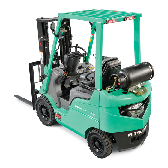
GENERAL INFORMATION 1. Model View Chapter 1 GENERAL INFORMATION MC truck 213447 FC truck 213448... - Page 11 Non-electric controlled gasoline engine, Truck type Non-electric controlled dual fuel gasoline/ LPG engine models Engine Engine Truck model Serial number Truck model Serial number mounted mounted FG10N F25C-05001 to FD10N F16D-04001 to S4Q2 FG15N F25C-55001 to FD15N F16D-54001 to S4Q2 FG15ZN F34-52001 to...
-
Page 12: Serial Number Locations
GENERAL INFORMATION 3. Serial Number Locations Name Plate Gasoline Engine Serial Number Chassis Serial Number Diesel Engine Serial Number (2, 3 ton classes) Diesel Engine Serial Number (1 ton class and FD20N–25N) Transmission Serial Number Mast Serial Number Transmission Serial Number (Powershift Transmission Truck) (Manual Transmission Truck) 213449... - Page 13 GENERAL INFORMATION 4. Dimensions 213450...
-
Page 14: Technical Data
GENERAL INFORMATION 5. Technical Data Unit: mm class 1 ton class FG10N FG15N FG18N FG20CN FGE15N FGE18N FGE20CN Gasoline- Truck model engine truck FG15ZN FG18ZN Diesel-engine FD10N FD15N FD18N FD20CN truck A Maximum lift 3000 3000 3000 3000 B Free lift height... - Page 15 GENERAL INFORMATION Unit: mm class 2 ton class 3 ton class FG20N FG25N FG30N FG35AN FGE20N FGE25N FGE30N FGE35AN Gasoline- Truck model engine truck FG20ZN FG25ZN FGE20ZN FGE25ZN Diesel-engine FD20N FD25N FD30N FD35AN truck A Maximum lift 3000 3000 3000 3000 B Free lift height C Fork spread...
- Page 16 FD18N FD20CN truck Capacity 1000 1500 1750 2000 Load center 490 (FG15N) 490 (FG18N) 570 (FG20CN) 490 (FG10N) 630 (FGE15N) 630 (FGE18N) 630 (FGE20CN) Loaded mm/s 570 (FG18ZN) 570 (FG15ZN) 630 (FD10N) 630 (FD15N) 630 (FD18N) 630 (FD20CN) Lift speed...
- Page 17 GENERAL INFORMATION class 2 ton class 3 ton class FG20N FG25N FG30N FG35AN FGE20N FGE25N FGE30N FGE35AN Gasoline- Truck engine truck FG20ZN FG25ZN model FGE20ZN FGE25ZN Diesel-engine FD20N FD25N FD30N FD35AN truck Capacity 2000 2500 3000 3500 Load center 520 (FG20N) 520 (FG25N) 580 (FGE20N) 580 (FGE25N)
- Page 18 Chapter 2 COOLING SYSTEM Specifications..................2-1 Structure ....................2-2 Removal and Installation................ 2-3 Fan Belt Removal ....................2-3 Suggestions for Removal ..................2-3 Installation ....................... 2-4 Inspection and Adjustment ..............2-5 Fan Belt Inspection....................2-5 Fan Belt Tension ..................... 2-5 Connecting Hoses ....................
-
Page 19: Cooling System
COOLING SYSTEM 1. Specifications Chapter 2 COOLING SYSTEM Truck type Items 1 ton class 2 ton class 3 ton class Cooling method Water-cooled, forced circulation Radiator Corrugated fin (pressure) type Cooling system Water pump Centrifugal type Thermostat Wax pellet type... - Page 20 COOLING SYSTEM 2. Structure Fan (directly coupled to engine) Radiator Shroud Hose layout S4Q2 engine Lower hose K15, K21, K25 engines Reservoir tank K15, K21, K25 S4Q2 Upper hose S4S engine 213451...
-
Page 21: Removal And Installation
COOLING SYSTEM 3. Removal and Installation 3.1 Fan Belt Removal Engine 213452 1 Tension pulley assembly, bolt 2 Belt 3.2 Suggestions for Removal (1) Loosen the tension pulley lock bolt by three or four turns. If the bolt is loosened insufficiently, the tension pulley will not move. - Page 22 BUY NOW Then Instant Download the Complete Manual Thank you very much! ...
Need help?
Do you have a question about the FG10N and is the answer not in the manual?
Questions and answers