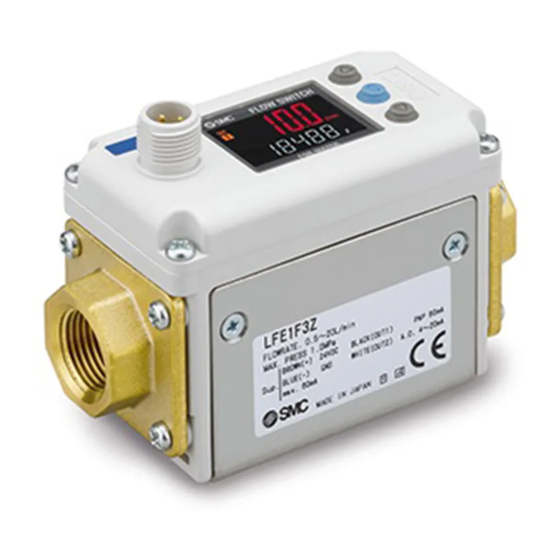
SMC Networks LFE Series Operation Manual
Electromagnetic digital flow switch remote type
Hide thumbs
Also See for LFE Series:
- Installation and maintenance manual (2 pages) ,
- Manual (25 pages) ,
- User manual (32 pages)

Related Manuals for SMC Networks LFE Series


Summary of Contents for SMC Networks LFE Series
- Page 1 Doc.No.LFE****-OMZ0012 Product Name Electromagnetic Digital Flow Switch Remote Type Model/ Series/ Product Number LFE#####(Z) SMC Corporation...
-
Page 2: Table Of Contents
Contents Safety Instructions Model Indication and How to Order Summary of Product Parts Definition and Terminology Mounting and Installation Installation Piping Method Wiring Maintenance and Inspection Troubleshooting Specifications Applicable Fluids and Precautions Characteristics Chart Analogue Output Dimensions No.LFE****-OMZ0012... -
Page 3: Safety Instructions
Safety Instructions These safety instructions are intended to prevent hazardous situations and/or equipment damage. These instructions indicate the level of potential hazard with the labels of “Caution,” “Warning” or “Danger.” They are all important notes for safety and must be followed in addition to International Standards (ISO/IEC) , and other safety regulations. - Page 4 Safety Instructions Caution The product is provided for use in manufacturing industries. The product herein described is basically provided for peaceful use in manufacturing industries. If considering using the product in other industries, consult SMC beforehand and exchange specifications or a contract if necessary. If anything is unclear, contact your nearest sales branch.
- Page 5 ■Explanation of Symbols S ym b o l Definition Things you must not do. Actual instructions are provided as a drawing or sentence close to this mark. Things you must do Actual instructions are provided as a drawing or sentence close to this mark. ■...
- Page 6 Caution Do not touch the terminals and connectors while the power is on. Otherwise electric shock, malfunction or damage to the switch can result. Do not touch Do not touch the piping joint or piping when hot fluid is used. It may lead to burn.
- Page 7 ● Product handling * Mounting - Tighten to the specified tightening torque. If the tightening torque is exceeded, the mounting screws, brackets and product may be damaged. Insufficient torque can cause displacement of the product from its proper position and the looseness of the mounting screws. - If a commercially available switching power supply is used, be sure to ground the frame ground (FG) terminal.
- Page 8 - Design and install the product so that fluid always fills the detection passage. 1. If the detection passage does not become fully filled with fluid during the use of the product, an incorrect detection signal can be generated in the electrodes, prohibiting correct measurement.
- Page 9 * Wiring (Including connecting/disconnecting of the connectors) - Do not pull the lead wire forcefully, or lift the product by the lead wire (Tensile strength 49 N or less). Hold the product body when handling. The lead wire will be damaged, leading to failure and malfunction. Damage to the connector, cover or internal components may result, causing failure or malfunction.
- Page 10 Operating environment - Do not use the product in an environment where the product is constantly exposed to water splashes. Otherwise failure or malfunction can result. Take measures such as using a cover. - Do not use in an environment where the product could be exposed to corrosive gas or liquids. Otherwise damage to the internal parts can result, causing malfunction.
- Page 11 * Adjustment and Operation - Check the load status before turning the power supply on. - Do not short-circuit the load. Over current may lead to the damage of the product. - Supply the power when there is no flow. - There will be a drift on the analogue output for 5 minutes after the power supply is turned on.
-
Page 12: Model Indication And How To Order
Model Indication and How to Order □□□□□ Rated flow range Isolation Specifications Symbol OUT2 Symbol Content Not isolated 0.5~ 20L/min Isolated 2.5~100L/min 5~200L/min Output Specifications Options Symbol OUT2 Lead wire and Symbol Bracket Analogue 1 to 5V M12 connector Analogue 4 to 20mA Thread type Port size Symbol... - Page 13 Combination of options Options available Without Lead wire and M12 connector With Lead wire and M12 connector Bracket Accessories/ Part number If an accessory is required, order using the following part number. Option Part No. Remarks Weight Lead wire and M12 LFE-1-A3 Lead wire length: 3 m Approx.
-
Page 14: Summary Of Product Parts
Summary of Product Parts Body Lead wire and M12 connector (4 pins) (Option) Connector Piping port Piping port Bracket (Option) Description Function The part to which “Lead wire and M12 connector” are connected. Connector Lead wire and M12 connector This is a cable that supplies power to the product and receives output. Piping port For piping connections. -
Page 15: Definition And Terminology
■ Definition and terminology Term Meaning Outputs a value proportional to the flow rate. When the analogue output is in the range 1 Analogue output to 5V, it will vary between 1 to 5V according to the rate of flow. The same for analogue output of 4 to -20 mA. -
Page 16: Mounting And Installation
Mounting and Installation Installation - Be sure to use the product within the specified operating pressure and temperature range. - Proof pressure is 2MPa. Proof pressure depends on fluid temperature. Refer to the chart of the operating pressure range (page 28). Mounting - Never mount the switch in a place that will be used as a scaffold. - Page 17 - When multiple sensors are used in parallel, install them at a distance as shown below. When multiple sensors are mounted in parallel within the area not suitable for installation, the detected flow rate may fluctuate. 20mm 20mm Area not suitable for installation -16- No.LFE****-OMZ0012...
-
Page 18: Installation
■ Installation Bracket mounting Fix the bracket using the mounting screws (Equivalent to M4: 4 pcs.). Bracket thickness is approx. 1.6mm Refer to the dimensions (page 30) for mouting hole sizes. Direct mounting Mount the product with the screw stated below. Nominal Tightening Thread type... -
Page 19: Piping Method
■ Piping Method When connecting the piping to the product, do not rotate the switch. Apply a spanner to the metal part of the piping port to turn the fitting.” Using a spanner on other parts may damage the product. Specifically, make sure that the spanner does not damage the M12 connector. - Page 20 Non-flexible piping materials such as steel piping will be subject to excessive moment load, vibration and impact from the piping side, so use a flexible tube for intermediate connection. Misaligned piping may apply long-term load after piping, causing malfunction, damage, or water leakage. Moment load Flexible piping Vibration...
-
Page 21: Wiring
Connector pin numbers (male connector) Wire color Pin description Brown DC (+) White OUT2 Cable connector Blue DC (-) Connector pin numbers (female connector) Black OUT1 *: When using the lead wire and M12 connector included with the LFE series. -20- No.LFE****-OMZ0012... - Page 22 Internal Circuit and Wiring examples Analogue voltage output type Analogue current output type LFE□J□□□(Z) LFE□K□□□(Z) Brown DC (+) Brown DC (+) Black NC Black NC White OUT2 White OUT2 24VDC 24VDC Load Load Blue DC (-) Blue DC (-) Analogue output 1 to 5 V Analogue output 4 to 20mA Load impedance 50 to 600 Ω...
-
Page 23: Maintenance And Inspection
Maintenance and Inspection How to reset the product after a power cut or when the power has been unexpectedly removed The settings for the product are retained in memory prior to the power loss or de-energizing of the product. The output condition is also recoverable to that prior to the power loss or de-energizing. However, this may change depending on the operating environment. -
Page 24: Troubleshooting
Troubleshooting Applicable products: LFE series If an operation failure occurs with the product, use the chart below to find out the cause of problem. If a cause applicable to the failure cannot be identified and normal operation can be recovered by replacement with a new product, this indicates that the product itself was faulty. -
Page 25: Specifications
Specifications ■ Specifications Model LFE1 LFE2 LFE3 Applicable Fluids Water, Conductive fluids which do not corrode the fluid contact materials 5μS/cm or more (micro Siemens/cm) Applicable fluidconductivity Detecting method Electro static cupacity Rated flow range 0.5 to 20 L/min 2.5 to 100 L/min 5 to 200 L/min Operating Fluid temperature 0 to 85... -
Page 26: Applicable Fluids And Precautions
■ Applicable Fluids and Precautions Applicable fluid list Substance description Judgment Remarks Conductivity of tap water: 100 to 200μS/cm Water Deionized water The electric conductivity is too low. Water base coolant When the ratio of water is 50% or more. The electric conductivity is too low. -
Page 27: Characteristics Chart
■ Characteristics Chart Flow rate characteristics (pressure loss) LFE1 LFE2 0.02 0.02 0.015 0.015 0.01 0.01 0.005 0.005 Flow rate [L/min] Flow rate [L/min] LFE3 0.02 0.015 0.01 0.005 Flow rate [L/min] -26- No.LFE****-OMZ0012... - Page 28 Straight pipe length (reference value) Straight Straight pipe length pipe length IN side OUT side Straight pipe length The smaller the piping size, the more the product is [Measurement condition] [Port size] affected by the straight piping length. Fluid: Tap water LFE1:3/8 inch The straight piping length shall be 5 times (5D) or Pressure: 0.2 MPa...
- Page 29 ■ Stability Fluctuation of the display and the analogue output can be reduced by lengthening the response time setting. ±4.0 ±3.5 ±3.0 ±2.5 ±2.0 ±1.5 ±1.0 ±0.5 ±0.0 応答時間[s] Response time[s] ■ Operating pressure range Operating range Fluid temperature [ When fluids with high temperature are used, the operating pressure range will be reduced.
-
Page 30: Analogue Output
■ Analogue output Flow/Analogue output Voltage output 1.1 V Current output 4 mA 4.4 mA 20 mA Rated flow [L/min] Model Minimum Maximum LFE1 LFE2 Flow rate Minimum Maximum LFE3 rated flow rated flow Out of range -29- No.LFE****-OMZ0012... -
Page 31: Dimensions
■ Dimensions 2XPort size Note) The electrical entry for lead wire with M12 connector does not rotate and is limited to only one entry direction. Without bracket (Bottom view) Bracket thickness is approx. 1.6mm Piping Model port size □ □□ 23.5 LFE1 □... - Page 32 ■ Lead wire and M12 connector (LFE-1-A3) Dimensions 4 Black Blue 3 1 Brown White 2 Cable specifications Item Specifications Nominal cross section AWG21 Conductor Outside diameter Approx. 0.9 mm Material Lead free heat resistant PVC Insulator Outside diameter Approx. 1.7 mm Colours Brown, White, Black, Blue Sheath...
- Page 33 Doc.No.LFE****-OMZ0012 Revision 4-14-1, Sotokanda, Chiyoda-ku, Tokyo 101-0021 JAPAN Tel: + 81 3 5207 8249 Fax: +81 3 5298 5362 https://www.smcworld.com Note: Specifications are subject to change without prior notice and any obligation on the part of the manufacturer. © 2021 SMC Corporation All Rights Reserved...
Need help?
Do you have a question about the LFE Series and is the answer not in the manual?
Questions and answers