Table of Contents
Advertisement
Quick Links
Advertisement
Table of Contents

Related Manuals for United Technologies Carrier Touchpilot 30XW-V

Summary of Contents for United Technologies Carrier Touchpilot 30XW-V
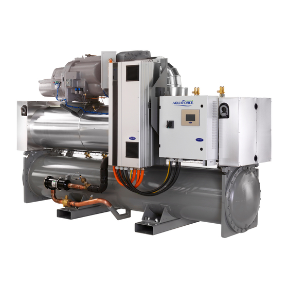
- Page 1 INSTALLATION, OPERATION AND MAINTENANCE INSTRUCTIONS Variable-Speed Water-Cooled Liquid Chillers/ Variable-Speed Water-to-Water Heat Pumps 30XW-V/30XWHV Nominal cooling capacity: 587-1741 kW Nominal heating capacity: 648-1932 kW 50 Hz Original instructions...
-
Page 2: Table Of Contents
CONTENTS 1 - INTRODUCTION ..................................4 1.1 - Installation safety considerations ............................4 1.2 - Equipment and components under pressure ........................5 1.3 - Maintenance safety considerations ............................5 1.4 - Repair safety considerations ..............................7 2 - PRELIMINARY CHECKS ..............................9 2.1 - Check equipment received .............................. - Page 3 9 - MAJOR SYSTEM COMPONENTS AND OPERATION DATA ..................22 9.1 - Compressors.................................... 22 9.2 - Oil filter ....................................22 9.3 - Refrigerant ....................................22 9.4 - Lubricant ....................................22 9.5 - Oil supply solenoid valve............................... 22 9.6 - Pressure vessels..................................22 9.7 - High-pressure safety switch ..............................
-
Page 4: Introduction
1 - INTRODUCTION The units can also be lifted with slings, using only the designated lifting points marked on the unit. 30XW-V/30XWHV units are designed to cool or heat water for the air conditioning and heating of buildings and Use slings or lifting beams with the correct capacity, and industrial procsses. -
Page 5: Equipment And Components Under Pressure
1.2 - Equipment and components under pressure The relief valve must only be removed if the fire risk is fully controlled and after checking that this is allowed by local regulations and authorities. This is the responsibility These products incorporate equipment or components under of the operator. - Page 6 If any maintenance operations are carried out on the unit, A logbook must be established for the systems that lock the power supply circuit in the open position ahead require a tightness check. It should contain the of the machine. quantity and the type of fluid present within the installation (added and recovered), the quantity of ATTENTION: The frequency variators used in the...
-
Page 7: Repair Safety Considerations
At least once a year thoroughly inspect the protection Ensure that you are using the correct refrigerant type devices (valves, pressure switches). If the machine operates before recharging the unit. in a corrosive environment, inspect the protection devices more frequently. Charging any refrigerant other than the original charge type (R-134a) will impair machine operation and can even Regularly carry out leak tests and immediately repair... - Page 8 Any refrigerant transfer and recovery operations must be The refrigerant lines can break under the weight and carried out using a transfer unit. A 3/8” SAE connector on release refrigerant, causing personal injury. the manual liquid line valve is supplied with all units for connection to the transfer station.
-
Page 9: Preliminary Checks
2 - PRELIMINARY CHECKS Before siting the unit check that: • the permitted loading at the site is adequate or that 2.1 - Check equipment received appropriate strenghtening measures have been taken. • the unit is installed level on an even surface (maximum •... -
Page 10: Dimensions, Clearances
3 - DIMENSIONS, CLEARANCES 30XW-V/30XWHV 580-880 Evaporator Condenser Dimensions in mm 30XW-V/30XWHV 1743 1087 3059 168.3 168.3 2900 1743 1087 3059 168.3 168.3 2900 1950 1083 1237 3290 219.1 219.1 3100 1950 1083 1237 3290 219.1 219.1 3100 Legend: All dimensions are given in mm. Required clearances for maintenance Recommended space for tube removal Water inlet... - Page 11 30XW-V/30XWHV 1150-1710 Evaporator Condenser Legend: All dimensions are given in mm. Required clearances for maintenance Recommended space for tube removal Water inlet Water outlet Power supply connection NOTES: Dimensions in mm • Drawings are not contractually binding. Before design- ing an installation, consult the certified dimensional 30XW-V/30XWHV 1150 1997...
-
Page 12: Physical And Electrical Data
4 - PHYSICAL AND ELECTRICAL DATA 4.1 - Physical data 30XW-V/30XWHV 1150 1280 1470 1570 1710 Sound levels - standard units Sound power level* dB(A) Sound pressure level at 1 m** dB(A) Sound levels - standard unit + option 257*** Sound power level* dB(A) Sound pressure level at 1 m**... -
Page 13: Electrical Data
4.2 - Electrical data 30XW-V/30XWHV 1150 1280 1470 1570 1710 Power circuit Nominal power supply V-ph-Hz 400-3-50 Voltage range 360-440 Control circuit 24 V via the built-in transformer Start-up current* Negligible (lower than maximum current drawn) Maximum power factor** 0.91-0.93 0.91-0.93 0.91-0.93 0.91-0.93... -
Page 14: Short-Circuit Stability Current For All Units
4.3 - Short-circuit stability current for all units 4.4 - Compressor electrical data Short-circuit stability current for all units using the TN Compressor nominal voltage/frequency: 380V/60Hz system (earthing system type): 50 kA (conditional system Compressor I Nom I Max LRDA Cosine phi Cosine (A)*... -
Page 15: Electrical Connection
5 - ELECTRICAL CONNECTION 5.3 - Power connection/disconnect switch Please refer to the certified dimensional drawings, supplied 30XW-V/30XWHV 580-880 units have one connection point with the unit. 30XW-V/30XWHV 1150-1710: • Standard unit: two connection points 5.1 - Power supply • Unit with option 81: one connection point. -
Page 16: Field Control Wiring
5.6 - Field control wiring 6 - APPLICATION DATA 6.1 - Operating limits IMPORTANT: Field connection of interface circuits may lead to safety risks: any control box modification must maintain equipment conformity with local regulations. 30XW-V/30XWHV Minimum Maximum Evaporator Precautions must be taken to prevent accidental electrical Entering temperature at start-up 35.0°C contact between circuits supplied by different sources:... -
Page 17: Minimum Chilled Water Flow
6.3 - Minimum chilled water flow 6.4 - Maximum chilled water flow The minimum chilled water flow is shown in the table in The maximum chilled water flow is limited by the permitted chapter 6.7 “Evaporator and condenser water flow rates”. pressure drop in the evaporator. -
Page 18: Minimum Temperature Difference
6.8 - Minimum temperature difference 6.9 - Variable flow evaporator The maximum flow rates recommended by Carrier limit Variable evaporator flow can be used. The controlled flow unit operation with a ∆T (entering - leaving) of 3 K in the rate must be higher than the minimum flow given in the sections shown below: table of permissible flow rates and must not vary by more... -
Page 19: Pressure Drop Curves
6.11 - Pressure drop curves 7 - WATER CONNECTIONS Units with two evaporator passes (standard) ATTENTION: Before carrying out any water connections install the water box purge plugs (one plug per water box in the lower section - supplied in the control box). For size and position of the heat exchanger water inlet and outlet connections refer to the certified dimensional drawings supplied with the unit. -
Page 20: Water Connections
Carrier recommendations on heat exchange fluids: If the water circuit must be emptied for longer than one • No NH ammonium ions in the water, they are very month, the complete circuit must be placed under nitrogen detrimental for copper. This is one of the most impor- charge to avoid any risk of corrosion by differential aeration. -
Page 21: Flow Control
7.3 - Flow control 7.5 - Operation of two units in master/slave mode Evaporator flow switch and chilled water pump interlock The control of a master/slave assembly is in the entering water and does not require any additional sensors (standard configuration). -
Page 22: Heat Pumps 30Xwhv
8 - HEAT PUMPS 30XWHV 9.5 - Oil supply solenoid valve 8.1 - Physical data for heat pumps An oil supply solenoid valve is installed on the oil return line as standard to isolate the compressor from oil flow The physical data for 30XWHV for heat pumps are the when the compressor is not operating. -
Page 23: High-Pressure Safety Switch
9.6.6 - Evaporator These pressure switches are located at the discharge of each 30XW-V/30XWHV units use a flooded multi-tube evaporator. compressor. The pressure switch tap does not include a The water circulates in the tubes and the refrigerant is on Schrader valve. -
Page 24: Options
10 - OPTIONS Options Description Advantages Use for 30XW- V range Light-brine solution, down to Implementation of new algorithms of control to allow chilled Matches with most application requirements 580-1710 (see -3°C brine solution production down to -3°C when ethylene glycol is for ground-sourced heat pumps and fits with dedicated used (0°C with propylene glycol) many industrial processes requirements paragraph) Master/slave operation Unit equipped with supplementary water outlet temperature Optimised operation of two chillers connected 580-1710 sensor kit to be field-installed allowing master/slave operation... -
Page 25: Standard Maintenance
11 - STANDARD MAINTENANCE • Clean the water filter (see chapter 7 “Water connec- tions”). • Check the unit operating parameters and compare Air conditioning equipment must be maintained by profes- sional technicians, whilst routine checks can be carried out them with previous values. -
Page 26: Tightening Torques For The Main Bolts And Screws
11.6 - Evaporator and condenser maintenance 11.4.2 - Connection precautions for the compressor power terminals These precautions must be applied during an intervention Check that: that requires the removal of the power conductors connected • the insulating foam is intact and securely in place, to the compressor supply terminals. -
Page 27: Frequency Variator Maintenance
11.9 - Service valve (option 92) The switch that has been selected for detecting reverse rotation is Carrier part number HK01CB001. This switch opens the contacts when the pressure falls below 7 kPa. The The unit can be equipped with optional service valves to switch is a manual reset type that can be reset after the facilitate maintenance and repair operations. -
Page 28: Start-Up Checklist For 30Xw-V/30Xwhv Units (Use For Job File)
12 - START-UP CHECKLIST FOR 30XW-V/30XWHV UNITS (USE FOR JOB FILE) Preliminary information Job name: ....................................... Location: ........................................ Installing contractor:..................................... Distributor: ......................................Unit Model: ........................................Compressors Circuit A Model number ....................................... Serial number ......................................Motor number ....................................... Circuit B Model number ....................................... Serial number ...................................... - Page 29 Unit start-up Oil level is correct All discharge and liquid line valves are open Locate, repair and mark all refrigerant leaks All suction valves are open, if used All oil line valves and economizer valves (if used) are open Checks have been carried out for any possible leaks. Unit has been leak checked (including fittings) - on the whole unit - at all connections Locate, repair, and report any refrigerant leaks ........................
- Page 32 www.eurovent-certification.com www.certiflash.com Order No: 13474-76, 05.2015. - Supersedes order No: 13474-76, 05.2013. Manufacturer: Carrier SCS, Montluel, France. Manufacturer reserves the right to change any product specifications without notice. Printed in the European Union.
Need help?
Do you have a question about the Carrier Touchpilot 30XW-V and is the answer not in the manual?
Questions and answers