Table of Contents
Advertisement
Quick Links
USER'S MANUAL
Of
Intel P45 Express Chipset
And
Intel ICH10 Chipset
Based
M/B for LGA775 Quad Core Ready
Intel Core Processor Family
NO. G03-HI04 -F
Rev:2.0
Release date: Aug., 2008
Trademark:
* Specifications and Information contained in this documentation are furnished for information use only, and are subject to
change at any time without notice, and should not be construed as a commitment by manufacturer.
Advertisement
Table of Contents

Related Manuals for Intel P45


Summary of Contents for Intel P45
- Page 1 USER'S MANUAL Intel P45 Express Chipset Intel ICH10 Chipset Based M/B for LGA775 Quad Core Ready Intel Core Processor Family NO. G03-HI04 -F Rev:2.0 Release date: Aug., 2008 Trademark: * Specifications and Information contained in this documentation are furnished for information use only, and are subject to...
- Page 2 Environmental Protection Announcement Do not dispose this electronic device into the trash while discarding. To minimize pollution and ensure environment protection of mother earth, please recycle.
-
Page 3: Table Of Contents
TABLE OF CONTENT USER’S NOTICE........................iii MANUAL REVISION INFORMATION ................iii COOLING SOLUTIONS ......................iii CHAPTER 1 INTRODUCTION OF P45 EXPRESS AND ICH10 MOTHERBOARDS FEATURES OF MOTHERBOARD ..................1 1-1.1 SPECIAL FEATURES OF MOTHERBOARD............ 2 SPECIFICATION........................4 PERFORMANCE LIST......................5 LAYOUT DIAGRAM ......................6 CHAPTER 2 HARDWARE INSTALLATION HARDWARE INSTALLATION STEPS................ -
Page 4: User's Notice
In addition, interface materials allow effective transfers of heat from the processor to the heat sink. For optimum heat transfer, Intel recommends the use of thermal grease and mounting clips to attach the heat sink to the processor. -
Page 5: Features Of Motherboard
Introduction of P45 Express and ICH10 chipset based Motherboards Features of Motherboard The P45 Express and ICH10 chipset motherboard series are based on Intel P45 Express chipset and ICH10 chipsets technology which supports the innovative 45nm and 65nm Quad-Core, Dual-Core Intel® Core 2 Quad, Core 2 Duo processors, Intel® Pentium Dual Core, Intel®... -
Page 6: 1-1.1 Special Features Of Motherboard
USB demands which are also equipped with hardware monitor function on system to monitor and protect your system and maintain your non-stop business computing. Some special features---CPU Thermal Throttling/ CPU Smart Fan/ CPU Vcore X-shift/ / DIY Clear/Power on Button/Reset Button in this Debug Port/OC-CON (optional) motherboard are designed for power user to use the over-clocking function in more flexible ways. - Page 7 The working temperature is from 55 degrees Centigrade below zero to 125 degrees Centigrade, OC-CON capacitors possess superior physical characteristics that can be while reducing the working temperature between 20 degrees Centigrade each time, intact extension 10 times of effective product operation lives, at not rising degrees Centigrade of working temperatures each time a relative one, life of product decline 10% only too.
-
Page 8: Specification
∗ PCI-Express2.0 x1 slot 1pcs Expansion Slot ∗ 32-bit PCI slot x 2pcs ∗ The Intel ICH10 supports six Serial ATA ports provide 3.0 Gb /sec data transfer rate. ∗ JMB363(Optional) Serial ATA RAID PCI-E controller that Integrate IDE and... -
Page 9: Performance List
Performance Test Report 1. Intel Core 2 Duo Conroe E6850 3.0GHz (C1E disable) 2. NEC 1.44M FDD / ASUS 50X CD-ROM 3. Crucial 1G DDR2-1066 X 2 2Gbyte Memory / Team group 1G DDR3-1066 X2 2Gbyte Memory 4. -
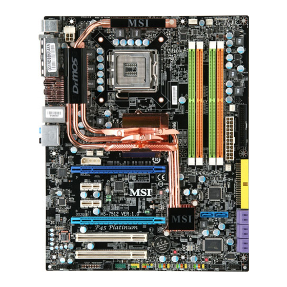
Page 10: Layout Diagram
USB Port LGA775 Socket RJ45 Over USB Conn. USB Power On Jumper (JP2) ATX Power Connector (Black) Audio Connector SYS FAN1 Intel P45 Express 4-pin PWR Connector Chipset PCI-E x16 by 16-laneI Intel ICH10 USB Power On Jumper (JP3) (Yellow) Chipset... - Page 11 Jumpers Jumper Name Description Page JBAT CMOS RAM Clear 3-pin Block Keyboard Power On Enabled/Disabled 3-pin Block JP2/JP3 USB Power On Enabled/Disabled 3-pin Block Connectors Connector Name Description Page ATXPWR ATX Power Connector 24-pin Block P.24 ATX12V ATX 12V Power Connector 8-pin Block P.24 CrossFire Power Connector...
-
Page 12: Chapter 2 Hardware Installation
Chapter 2 Hardware Installation WARNING! Turn off your power when adding or removing expansion cards or other system components. Failure to do so may cause severe damage to both your motherboard and expansion cards. Hardware installation Steps Before using your computer, you had better complete the following steps: 1. -
Page 13: Glossary
(2) Keyboard function Enabled/Disabled: JP1 2-3 Closed KB Power ON Enabled 1-2 Closed KB Power ON Disable (Default) Keyboard/Mouse Power On Setting (3) USB Power On function Enabled/Disabled: JP2/JP3 JP2 / JP3 JP2 / JP3 1-2 closed USB Power On Disable 2-3 closed USB Power On Enabled (Default) USB Power-On Setting... -
Page 14: About Intel Lga775 Cpu
2-3-2 About Intel LGA775 CPU This motherboard provides a 775-pin DIP, LGA775 Land Grid Array socket, referred to as the LGA775 socket supports Intel Pentium 4 processor in the 775 Pin package utilizes Flip-Chip Land Grid Array (FC-LGA) package technology. -
Page 15: Lga 775 Cpu Installation Guide
2-3-3 LGA 775 CPU Installation Guide Socket Preparation 1. Opening the socket: Note: Apply pressure to the corner with right hand thumb while opening/closing the load lever, otherwise lever can bounce back like a “mouse trap” and WILL cause bent contacts (when loaded) Socket Load Plate Open... - Page 16 3. Visually inspect for bent contacts (Recommend at least 1stpass visual inspection) NOTE: Refer to the Handling and Inspection Module for 1stand 2ndpass inspection details. NOTE: Glove images are for illustrative purposes only. Please consult local safety guidelines for specific requirements NOTE: Recommend not to hold the load plate as a lever, instead hold at tab with left hand, removing the PnP cap with right hand 775- Land LGA Package Insertion...
- Page 17 775- Land Package Removal Open the Load Plate/Lever with both hands: With left hand index finger and thumb to support the load plate edge, engage PnP cap with right hand thumb and peel the cap from LGA775 Socket while pressing on center of PnP cap to assist in removal. Pick up 775-land LGA package: By Vacuum Pen: Place a minimum 9-mm cup at approximately the center of IHS.
- Page 18 Secure/Hook the back side of PnP cap. Snap down the front side to fully secure 7. Close the Socket Intel Reference Thermal Solution Assembly NOTE: Depending on the configuration, Thermal Solution Integration procedure could perform with M/B alone or with M/B in the Chassis.
- Page 19 NOTE: Thermal Solutions that come with IntelR boxed processor use pre-applied thermal interface material Apply Thermal and not grease. Interface Material Remove Heat Sink (HS) from packaging media Place HS onto the LGA775 Socket • Ensure fan cables are oriented on side closest to fan header •...
- Page 20 Intel Reference Thermal Solution Disassembly Rotate fastener cap. turn to un-lock Pull up fastener cap to un-seat 12 Disconnect fan cable from motherboard header Turn fastener caps (4) counter-clock wise 90degrees to the un-locked position • A flat-bladed screwdriver may be used if required Pull up on fastener caps to unseat Manually remove HS with gentle twist motion.
- Page 21 Remove the heatsink from the socket Gently push loose thermal interface material (TIM) to center of processor (pictures 2 and 3) Remove pieces with dry cloth (picture 4) Wipe with dry, lint-free cloth to remove most of the material (picture 5) Wet another lint-free cloth with isopropyl alcohol (IPA) and wipe to clean remaining material (picture 6) Be careful to remove material from gaps between processor and load plate...
- Page 22 − Set on heatsink side or with fan down • The plastic fasteners on the heatsink can be replaced. − Use Shop Intel to order spare fasteners − http://www.shop-Intel.com • To remove a damaged fastener Note: Protective gloves are not required for this procedure −...
- Page 23 Tilt to remove Replacing Fasteners • To replace the fastener − Start with the white prong − Note the “keying” notch feature − Tilt the prong to insert into the heatsink leg. − Holding the white prong without bending it, push the black pin on from the bottom until you hear a single “click”...
-
Page 24: Installing Memory
Installing Memory This motherboard provides four 240-pin DDR2 DUAL INLINE MEMORY MODULES (DIMM) socket for DDR2 memory expansion available from minimum memory volume of 128MB to maximum memory volume of 16GB DDR SDRAM . Valid Memory Configurations for DDR2 Bank 240-Pin DIMM Total Memory Bank 0, 1 (DIMM1) -
Page 25: Expansion Card
Expansion Cards 2-5-1 Procedure For Expansion Card Installation 1. Read the documentation for your expansion card and make any necessary hardware or software setting for your expansion card such as jumpers. 2. Remove your computer’s cover and the bracket plate on the slot you intend to use. 3. -
Page 26: Pci-Express Slot
2-5-3 PCI Express Slot The P45 Express chipset Based motherboard series offer two PCI-Express2.0 x16 graphics slots (One PCI-Express2.0 x16@16lane graphics slot offers 8 Gbyte/sec data transfer rate at each relative direction which get 7 times of bandwidth more than AGP8X and up to 16Gbyte/sec concurrent bandwidth at full speed, the other PCI-Express x16@8lane graphics slots deliver up to 4Gbyte/sec data transfer rate at each relative direction .These two graphics... -
Page 27: Installing The Crossfire Bridge Card
2-5-4 Installing the CrossFire Bridge Card The following illustrations show you how to install the CrossFire Bridge Card. Bridge for CrossFire Tech. Supported VGA Cards (For AMD 790FXCrossFire Tech. Motherboards Only) In order to activate the CrossFire technology, you have to install the optional CF Bridge for your CrossFire Tech. -
Page 28: Connectors, Headers
Connectors, Headers 2-6-1 Connectors Power Connector (24-pin block): ATXPWR ATX Power Supply connector: This is a new defined 24-pins connector that usually comes with ATX case. The ATX Power Supply allows using soft power on momentary switch that connect from the front panel switch to 2-pins Power On jumper pole on the motherboard. - Page 29 Pin 1 (3) PS/2 Mouse & PS/2 Keyboard Connector: KB The connectors are for PS/2 keyboard and PS/2 Mouse input devices. (4) USB Port connector: from US1, US2,UL1 The connectors are 4-pin connectors that connect USB devices with the 400Mbit / sec data transfer rate to the system board.
- Page 30 Line-In Surback CEN/LEF Line-Out Surround MIC-In (8) Floppy drive Connector (34-pin block): FLOPPY This connector supports the provided floppy drive ribbon cable. After connecting the single plug end to motherboard, connect the two plugs at other end to the floppy drives. FLOPPY (Black)...
-
Page 31: Headers
(10) Serial-ATA2 Port connectors: DSATA1 / DSATA2 / DSATA3 These connectors support the provided Serial ATA and Serial ATA2 IDE hard disk cable to connect the motherboard and serial ATA2 hard disk drives. DSATA3 DSATA2 DSATA1 Serial-ATA2 Compatible Connectors (11) ESATA Port(Optional for HI04 series only): ESATA ports from US1,US2 These two connectors support the External Serial ATA2 (eSATA) to enable the full SATA interface speed outside the chassis. - Page 32 (2) USB Port Headers (9-pin): USB1/USB2/ USB3 These headers are used for connecting the additional USB port plugs. By attaching an option USB cable, your can be provided with two additional USB plugs affixed to the back panel. USB2 USB3 USB1 Pin 1 Pin 1...
- Page 33 CPUFAN SYSFAN2 SYSFAN1 (9) CD Audio-In Headers (4-pin) : CDIN CDIN are the connectors for CD-Audio Input signal. Please connect it to CD-ROM CD-Audio output connector. C DIN CD Audio-In Headers (10) IR infrared module Headers (5-pin): IR This connector supports the optional wireless transmitting and receiving infrared module.
- Page 34 Pin 1 PARALLEL Connector (12) Serial COM Port header: COM1 COM1 is a 9-pin RS232 connector. Pin1 Serial COM Port 9-pin Block (13) SPDIF Out header: HDMI_SPDIF The SPDIF output is capable of providing digital audio to external speakers or compressed AC3 data to an external Dolby digital decoder.
-
Page 35: Starting Up Your Computer
Starting Up Your Computer 1. After all connection is made, close your computer case cover. 2. Be sure all the switch are off, and check that the power supply input voltage is set to proper position, usually in-put voltage is 220V∼240V or 110V∼120V depending on your country’s voltage used. -
Page 36: Chapter 3 Introducing Bios
Chapter 3 Introducing BIOS The BIOS is a program located on a Flash Memory on the motherboard. This program is a bridge between motherboard and operating system. When you start the computer, the BIOS program will gain control. The BIOS first operates an auto-diagnostic test called POST (power on self test) for all the necessary hardware, it detects the entire hardware device and configures the parameters of the hardware synchronization. -
Page 37: The Main Menu
The Main Menu Once you enter Award ® BIOS CMOS Setup Utility, the Main Menu (Figure 3-1) will appear on the screen. The Main Menu allows you to select from fourteen setup functions and two exit choices. Use arrow keys to select among the items and press <Enter> to accept or enter the sub-menu. -
Page 38: Standard Cmos Features
Use this menu to load the BIOS default values that are factory settings for optimal performances system operations. Load Standard Defaults Use this menu to load the BIOS default values for the minimal/stable performance system operation. Save & Exit Setup Save CMOS value changes to CMOS and exit setup. -
Page 39: Advanced Bios Features
If the controller of HDD interface is SCSI, the selection shall be “None”. If the controller of HDD interface is CD-ROM, the selection shall be “None” Access Mode The settings are Auto Normal, Large, and LBA. Cylinder number of cylinders Head number of heads Precomp... -
Page 40: Advanced Chipset Features
The BIOS attempts to load the operating system from the devices in the sequence selected in these items. The settings are Floppy, LS120, Hard disk, CDROM, ZIP100,USB-FDD, USB-ZIP, USB-COROM, Legacy LAN and Disabled. Boot Other Device The settings are: Enabled and Disabled. Boot Up Floppy Seek During POST, BIOS will determine if the floppy disk drive installed is 40 or 80 tracks. -
Page 41: Integrated Peripherals
↑↓→← Move Enter:Select +/-/PU/PD:Value F10:Save ESC:Exit F1:General Help F5:Previous Values F6:Optimized Defaults F7:Standard Defaults System BIOS Cacheable Selecting Enabled allows caching of the system BIOS ROM at F0000h-FFFFFh, resulting in better system performance. However, if any program writes to this memory area, a system error may result. -
Page 42: Onboard Device Function
3-7-2 Onboard Device Function Phoenix – AwardBIOS CMOS Setup Utility Onboard Device Function Onboard PCIE LAN Controller Enabled Item Help Onboard PCIE LAN BootROM Disabled JMicro Controller Enabled JMicro Controller Mode IDE Mode Menu Level >> High Definition Audio Enabled USB Host Controller Enabled USB 2.0 Controller... -
Page 43: Onboard Super Io Function
UART2 Mode Select This item allows you to determine which InfraRed(IR) function of the onboard I/O chip, this functions uses. IrDA Duplex Mode This field is available when UART Mode is set to either ASKIR or IrDA. This item enables you to determine the infrared function of the onboard infrared chip. -
Page 44: Power Management Setup
Power Management Setup The Power Management Setup allows you to configure your system to most effectively save energy saving while operating in a manner consistent with your own style of computer use. Phoenix – AwardBIOS CMOS Setup Utility Power Management Setup ACPI Function Enabled Item Help... -
Page 45: Miscellaneous Control
Power On by Ring During Disabled, the system will ignore any incoming call from the modem. During Enabled, the system will boot up if there’s an incoming call from the modem. Resume by Alarm This function is for setting date and time for your computer to boot up. During Disabled, you cannot use this function. -
Page 46: Pc Health Status
3-10 PC Health Status This section shows the Status of you CPU, Fan, and Warning for overall system status. This is only available if there is Hardware Monitor onboard. Phoenix – AwardBIOS CMOS Setup Utility PC Health Status Shutdown Temperature Disabled Item Help Show PCHealth in POST... -
Page 47: Power User Overclock Setting
3-12 Power User Overclock Setting Phoenix – AwardBIOS CMOS Setup Utility Power User Overclock Settings Linear PCIEX Clock 100MHz CPU Diff AMP Control 800MHZ Item Help CPU Clock Ratio ** Current DRAM CLOCK 800 MHz ** DRAM Clock at Next Boot Auto/800MHz Menu Level >... -
Page 48: Cpu Feature
Limit CPU ID Maxval Disabled C1E Function Enabled Menu Level > Execute Disabled Bit Enabled Enhanced Intel Speed Step Tech Enabled ↑↓→← Move Enter:Select +/-/PU/PD:Value F10:Save ESC:Exit F1:General Help F5:Previous Values F6:Optimized Defaults F7:Standard Defaults 3-12-2 DRAM Timing Setting Phoenix – AwardBIOS CMOS Setup Utility... -
Page 49: Load Standard/Optimized Defaults
ENTER PASSWORD: Type the password, up to eight characters in length, and press <Enter>. The password typed now will clear any previously entered password from CMOS memory. You will be asked to confirm the password. Type the password again and press <Enter>. You may also press <Esc> to abort the selection and not enter a password. -
Page 50: Chapter 4 Driver & Free Program Installation
If the menu does not appear, double-click MY COMPUTER / double-click CD-ROM drive or click START / click RUN / type X:\SETUP.EXE (assuming X is your CD-ROM drive). The Intel P45 chipset driver only of Windows 2000 & Windows XP From MAGIC INSTALL MENU you may make 10 selections: 1. -
Page 51: Inf Install Intelp45 Chipset System Driver
4-1 INF Install Intel P45 Chipset System Driver 1. Click INF of the MAGIC INSTALL MENU. 2. Click NEXT when Intel Chipset Device Software Install Utility appears. 3. Click Yes to accept the license agreement and 4. Finish reading the read me information and continue the installation. -
Page 52: Sound Install Alc888 Hd Codec Audio Driver
SOUND Install ALC888 HD Codec Audio Driver 1. Click SOUND when MAGIC INSTALL 2. Click NEXT When Realtek High Definition MENU appears Audio driver windows appear 3. Click FINISH and restart your computer 4. Manual Sound Effect Setting 5. The mixer. 6. -
Page 53: Lan Install Realtek Gigabit Ethernet Nic Driver
1. Click LAN when Magic Install Menu appear. 2. Click NEXT, install REALTEK LAN and Fast Ethernet NIC Driver 3. Click install to begin the installation. 4. After driver installation completed, Click Finish. Install Intel USB2.0 Driver 4-4 USB2.0 Windows 2000 OS Please install Windows 2000 service pack 4 or later. Windows XP OS... -
Page 54: Raid Install Jmicron Raid Driver
4-5 RAID Install JMICRON RAID Driver (for HI04 Only) Click RAID when MAGIC INSTALL Click “Next” when the "JMB36X RAID MENU appears. Configurer" installShield Wizard appears To select the setup type that best suits your Click the “Install” to begin the installation. need Choose whether you would like to restart your computer and then Click FINISH to... -
Page 55: Pc-Cillin Install Pc-Cillin 2007 Anti-Virus Program
4-6 PC-CILLIN Install PC-CILLIN 2007 Anti-virus Program Click PC-CILLIN when MAGIC INSTALL Select “Next” when the "Trend Micro MENU appears. PC –Cillin internet security 2007" windows appears. This is the license agreement, select "I The preinstallation checkup process. Accept the terms" and Click NEXT. Click Next after you select the features you 6. -
Page 56: Pc-Health Install Myguard Hardware Monitor Utility
1. Click PC-HEALTH when MAGIC INSTALL 2. Click Next when Install shield wizard Window MENU appears appears 3. Click Install to begin the installation. 4. Click Finish to complete the installation. NOTE: MAGIC INSTALL will auto detect file path X:\P45\MYGUARD\SETUP.EXE... -
Page 57: Raid Disk Install Jmicron X32 Raid Disk
STEP 2. Copy utility program to your boot disc. You may copy from DRIVER CD X:\FLASH\AWDFLASH.EXE or download from our web site. STEP 3. Download and make a copy of the latest BIOS for P45 series motherboard series from the web site to your boot disc. - Page 58 Step2. Reboot the computer and press Ctrl+ J when the following window appears: The name disks you would like to set RAID function should appear under the Hard Disk Driver List category on the right window. Choose Create RAID Disk Drive and press Enter, then the following windows will show up:...
-
Page 59: Pro Magic Plus Function Introduction
success in creating RAID mode. Step3. How to make a RAID driver diskette? 1: Insert the diskette which is being formatted in floppy drive on a system which can start OS. 2: After booting OS insert the bundle CD in your CD-ROM 3: Copy all the files from \NF-orce4\RAIDDisk to floppy diskette Once you have the SATA driver diskette ready, you may start to install Windows XP or Windows 2000 on your System. - Page 60 ◇ Support Only Windows OS (No Linux) ◇ Windows server OS and Windows NT not supported ◇ Minimum of Intel 486 or above, 16MB of memory or above ◇ Minimum of 500MB free/usable space or above ◇ Support for SCSI & SATA Hard disk...
- Page 61 APPENDIX Debug Port Post Code Normal POST Codes NOTE: EISA POST codes are typically output to port address 300h. ISA POST codes are output to port address 80h. Code(hex) Name Description Turn Off Chipset OEM Specific-Cache control cache And CPU test Processor Status (1FLAGS) Verification.
- Page 62 Code(hex) Name Description Reserved Blank video Reset Video controller Reserved Init KBC Keyboard controller init KB test Test the Keyboard Reserved Mouse Init Initialized the mouse Onboard Audio init Onboard audio controller initialize if exist Reserved Reserved CheckSum Check Check the intergraty of the ROM,BIOS and message Reserved Auto detec EEPROM...
- Page 63 Test DMA Controller Test DMA channel 0 Reserved Test DMA Controller Test DMA channel 1 Reserved Test DMA Page Test DMA Page Registers. Registers Reserved Reserved Test Timer Counter 2 Test 8254 Timer 0 Counter 2. Reserved Test 8259-1 Mask Verify 8259 Channel 1 masked interrupts by Bits alternately turning off...
- Page 64 Onboard I/O Init Initializing onboard superIO Reserved Reserved Setup enable Display setup message and enable setup functions Reserved Reserved Initialize & Install Detect if mouse is present, initialize Mouse mouse, install interrupt vectors. Reserved PS2 Mouse special Special treatment to PS2 Mouse port Reserved ACPI init ACPI sub-system initializing...
- Page 65 Reserved Reserved Reserved Reserved Reserved Reserved Reserved Boot Medium Read and store boot partition head and detection cylinders values in RAM Final Init Final init for last micro details before boot Special KBC patch Set system speed for boot Setup NumLock status according to Setup Boot Attempt Set low stack...
- Page 66 and turn on all necessary CPU features Display PnP logo and PnP early init Setup virus protect according to Setup. If required, will auto load Awdflash.exe in POST Initializing onboard superIO Reserved Reserved Reserved Reserved Setup Init Display setup message and enable setup functions Detect if mouse is present, initialize mouse, install interrupt vectors.
- Page 67 S4 POST Codes Code(hex) Name Description Early Chipset Init Early Initialized the super IO Reset Video controller Keyboard controller init Test the Keyboard Initilized the mouse Cmos Check Check Cmos Circuitry and reset CMOS Chipset default Program the chipset registers with Prog CMOS values.
- Page 68 KB init Initialized KBC Install interrupt Install int. vector (0-77), and vectors initialized 00-1fh to their proper place Init Video Video initializing Init FDD Scan floppy and media capacity for onboard superIO Boot Load boot sector...
Need help?
Do you have a question about the P45 and is the answer not in the manual?
Questions and answers