
Related Manuals for Safety POWELL PowlVac-ND 4 Series

Summary of Contents for Safety POWELL PowlVac-ND 4 Series
- Page 1 DRAFT Powered by Safety ® Instruction Bulletin - 01.4IB.77020 PowlVac-ND® and PowlVac-NDA™ Series 4 Vacuum Circuit Breakers 5kV / 1200A & 2000A / 36kA & 50kA...
- Page 2 PowlVac-ND® and PowlVac-NDA™ Series 4 01.4IB.77020 Vacuum Circuit Breakers Contact Information Powell Electrical Systems, Inc. powellind.com info@powellind.com Service Division 7232 Airport Blvd. Houston, Texas 77061 713.944.6900 phone 713.948.4569 fax Powered by Safety Powered by Safety ® ®...
- Page 3 As stated in ANSI Z535.4-2007, the signal word is For the purposes of this manual, a qualified a word that calls attention to the safety sign and person, as stated in NFPA 70E®, is one who has designates a degree or level of hazard seriousness.
- Page 4 PowlVac-ND® and PowlVac-NDA™ Series 4 01.4IB.77020 Vacuum Circuit Breakers This page is intentionally left blank. Powered by Safety ®...
-
Page 5: Table Of Contents
B. p ................................2 urpoSe c. I ....................2 nStructIon ulletInS vAIlABle lectronIcAlly D. A ............................2 SSocIAteD ulletInS Ch 2 Safety ........................3 A. S ............................3 onDItIon B. S ...............................3 Afety uIDelIneS c. G ................................4 enerAl D. S ................................4 pecIfIc e. X-r ................................5... - Page 6 2) Inspection and Cleaning ..............................44 B. M ............................. 45 echAnISM 1) Mechanical Operation .................................45 2) Lubrication ....................................45 3) Closing Spring Removal ...............................49 4) Slow Closing of Mechanism ..............................50 5) Mechanism Adjustments ..............................50 6) Electrical Operation ................................55 Powered by Safety ®...
- Page 7 4) Secondary Shunt Trip Coil Assembly ..........................59 5) Undervoltage Device Assembly ............................59 6) Charging Motor Assembly ..............................59 7) Anti-Pump Relay Assembly ..............................59 8) Latch Check Switch ................................59 9) Motor Cutoff Switch Assembly ............................59 10) Auxiliary Switch ..................................59 Powered by Safety ®...
- Page 8 Table A Field Dielectric Test Values .................26 Table B Lubrication ......................46 Table C Timing .........................57 Table D Primary Resistance .....................57 Table E Primary Current Path ..................60 Table F Control Devices ....................61 Table G Miscellaneous Parts ...................63 Powered by Safety ®...
- Page 9 01.4IB.77020 This page is intentionally left blank. Powered by Safety ®...
- Page 10 Powell at 1.800.480.7273. NOTICE Powell reserves the right to discontinue and to change specifications at any time without incurring any obligation to incorporate new features in products previously sold. Powered by Safety ® General Information...
-
Page 11: Ch 1 General Information
A. S cope WARNING This instruction bulletin is intended to assist Follow the appropriate safety precautions users in the design and safe operation of while handling any of the equipment. Failure these PowlVac-ND® and PowlVac-NDA™ circuit to do so may result in death or serious injury. -
Page 12: P Urpose
3. Wherever possible, visually verify that all Informational Note No. 1: See UL 61010-1, blades of the disconnecting devices are Safety Requirements for Electrical Equipment fully open or that drawout-type circuit for Measurement, Control, and Laboratory breakers are withdrawn to the fully Use, Part 1: General Requirements, for disconnected position. -
Page 13: S Afety G Uidelines
Furthermore, each user has the responsibility of establishing a safety program for each type of a.. Placement. Temporary protective equipment encountered. grounding equipment shall be placed... -
Page 14: G Eneral
CIRCUIT BREAKERS. 7. Interlocks are provided to ensure the proper operating sequences of the circuit breakers and for the safety of the user. If for any reason an interlock does not function as described, do not make any adjustments, modification, or deform the parts. DO NOT FORCE THE PARTS INTO POSITION. -
Page 15: X-R Ays
(3’) from the front of the circuit breaker. THE CIRCUIT BREAKER SHALL BE EITHER FULLY OPEN, OR FULLY CLOSED WHEN MAKING HIGH POTENTIAL TESTS. DO NOT TEST WITH CONTACTS PARTIALLY OPEN. Powered by Safety ® Equipment Description... -
Page 16: Ch 3 Equipment Description
(Figure 3, al). In rear of the circuit breaker frame prior to the same metal enclosed compartment as the installing the escutcheon. stored energy mechanism is the circuit breaker Powered by Safety ® Equipment Description... - Page 17 (Figure 4, ac). The spring charge indicator (Figure 3, o) will display that the mechanism is charged. Powered by Safety ® Equipment Description...
-
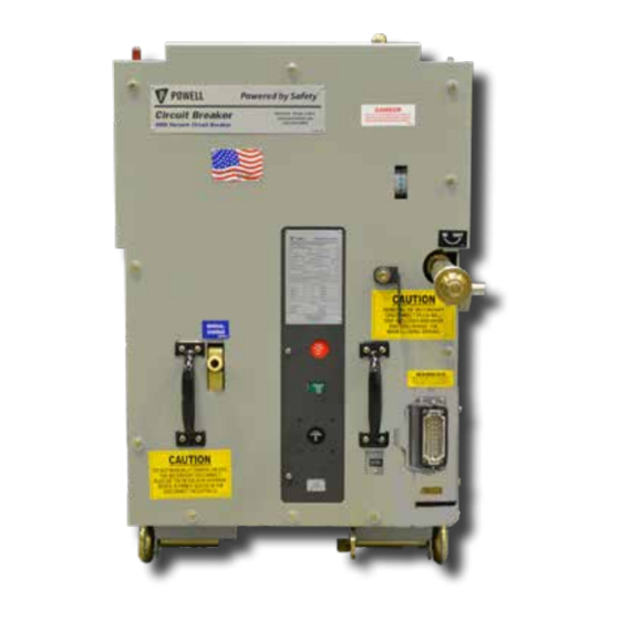
Page 18: Figure 1 Typical Powlvac-Nd® Series 4 Vacuum Circuit Breaker
01.4IB.77020 Figure 1 Typical PowlVac-ND® Series 4 Vacuum Circuit Breaker Figure 2 Typical PowlVac-NDA™ Series 4 Vacuum Circuit Breaker Powered by Safety ® Equipment Description... -
Page 19: Figure 3 Powlvac-Nda™ Circuit Breaker - Exterior View
Circuit Breaker Open/Closed Indicator w. Lower Primary Disconnecting Device aj. Spring Yoke Secondary Disconnect Latch Frame ak. Contact Loading Spring Manual Close Operator Ground Connection al. Operating Pushrod m. Secondary Disconnect Receptacle Serial Number Plate Location Powered by Safety ® Equipment Description... -
Page 20: Figure 4 Powlvac-Nda™ Circuit Breaker - Interior View
Motor Cutoff Cam Secondary Trip Prop Crank Pin ad. Close Bar Adjusting Screw Main Cam Roller Holding Pawl Adjusting Eccentric ae. Charging Motor Drive Shaft Reset Spring Crank Arm af. Motor Cutoff Switch Powered by Safety ® Equipment Description... -
Page 21: Figure 5 Cam And Fundamental Linkage Positions
Figure 5 Cam and Fundamental Linkage Positions b) Breaker Closed - Spring Discharged a) Breaker Open - Spring Charged - Links Reset c) Breaker Open - Spring Discharged d) Breaker Closed - Spring Charged Powered by Safety ® Equipment Description... -
Page 22: Figure 6 Mechanism And Trip Linkages
Secondary Linkage Roller e. Main Cam Roller f. Reset Spring g. Camshaft h. Main Closing Cam Center Phase Operating Lever Jackshaft k. Primary Trip Prop Roller Primary Trip Prop Adjusting Screw m. Primary Trip Prop Powered by Safety ® Equipment Description... - Page 23 Further movement of the operating pushrod assembly compresses the contact loading spring even more and produces a gap between the face of the spring yoke and the lock nut. Powered by Safety ® Equipment Description...
-
Page 24: Figure 7 Operation Sequence
SET UP ENERGIZED RELEASE CLOSE MAKES BREAKS BREAKS MAKES CONTROL SWITCH "CS/C" BREAKS WHITE LIGHT MOTOR "M" ENERGIZED DE-ENERGIZED "Y" COIL DE-ENERGIZED "Y" CONTACT BREAKS PREVENTS PUMPING IF VCB TRIPS BEFORE CONTROL SWITCH IS RELEASED Powered by Safety ® Equipment Description... -
Page 25: Figure 8 Typical Control Scheme
52/b = BREAKER AUXILIARY CONTACT (NORMALLY CLOSED) SD = BREAKER SECONDARY DISCONNECT ( ) TB = TERMINAL BLOCK RM = RACKING MOTOR UV = UNDERVOLTAGE TRIP COIL ER = EMERGENCY RACKING ISOLATION SWITCH CBM = CIRCUIT BREAKER MONITORING (FRONT VIEW) Powered by Safety ® Equipment Description... -
Page 26: Electrical Description
Powered by Safety ® Equipment Description... -
Page 27: R 1) General Description
Figure 7. Circuit E. Racking Procedures for the breaker mounted auxiliary contacts not PowlVac-ND® Series 4 Circuit Breaker used in the control circuit are brought for more information. out for control and indication functions. Powered by Safety ® Equipment Description... - Page 28 • The circuit breaker cannot be racking crank arms are fully in the removed from the circuit breaker test/disconnected position. compartment with the circuit breaker closed or with the main closing spring charged. Powered by Safety ® Equipment Description...
-
Page 29: Closed Door Racking Mechanism
Rotation of the racking crank arms will drive the circuit breaker into or out of the connected position. This action also operates the compartment shutters. Powered by Safety ® Equipment Description... -
Page 30: A Utomatic Acking Echanism Or Owl Ac -Nda™ S Eries Ircuit Reaker
Upon initial insertion of the circuit breaker into the compartment, a position interlock prevents moving the circuit breaker from the disconnected position to the test position without the secondary disconnect inserted. Powered by Safety ® Equipment Description... -
Page 31: Racking Mechanism
This blocks the operation of the emergency racking drive shaft, deterring any attempt to remove a closed circuit breaker from the compartment. Powered by Safety ® Equipment Description... -
Page 32: Ircuit B Reaker C Ompartment I Nterfaces
The ground connection system remains positions of the circuit breaker. engaged in all subsequent positions of the circuit breaker until the circuit breaker is removed from the compartment. Powered by Safety ® Equipment Description... -
Page 33: Shutter Rollers
PowlVac-ND® Series 4 and PowlVac-NDA™ Series 4 circuit breakers see Table E, Primary Path. VACUUM INTERRUPTERS Current MUST BE REPLACED ONLY WITH NEW VACUUM INTERRUPTERS OF THE SAME PART NUMBER. Powered by Safety ® Equipment Description... -
Page 34: Ch 4 Installation
The circuit breaker can also be lifted by an overhead crane using the two lifting holes which have been provided for hooks at the top of the circuit breaker frame side sheets (Figure 11). Powered by Safety ® Installation... -
Page 35: S Torage
Space heaters within the equipment should be energized, if so equipped. Humidity controlling desiccant materials should be utilized when space heaters are not provided or cannot be energized. The Powered by Safety ® Installation... -
Page 36: P Lacing The C Ircuit B Reaker I Nto S Ervice
DC testing is not the preferred method, however, values are provided due to the availability of DC test CAUTION sets. Remove all grounding conductors applied for this test before placing the circuit breaker back into service. Powered by Safety ® Installation... -
Page 37: Vacuum Integrity
(Hipot) used to for circuit breaker with a rated maximum determine “High voltage insulation voltage of 4.76kV. integrity.” See Ch 4 Installation, D. Placing the Circuit Breaker Into Service, 1) High Voltage Insulation Integrity. Powered by Safety ® Installation... -
Page 38: Control Voltage Insulation Integrity
DC leakage current. motor when the tests are complete. There is no significant correlation. CAUTION Remove all grounding conductors applied for this test before placing the circuit breaker back into service. Powered by Safety ® Installation... -
Page 39: Mechanical Operation Check
Lift the handle until it is horizontal and then depress. The procedure is repeated until the spring charge indicator indicates “CLOSING SPRING CHARGED”. This requires about 60 operations of the handle. Once the closing spring is charged, remove the handle. Powered by Safety ® Installation... -
Page 40: Electrical Operation Check
SCADA, or automatic transfer schemes. Powered by Safety ® Installation... -
Page 41: Acking P Rocedures For P Owl V Ac -Nd® S Eries 4 C Ircuit B Reaker
Do not attempt to force the circuit minor or moderate injury. breaker past the compartment interference plate or remove the interference plates from either the compartment or the circuit breaker. Powered by Safety ® Installation... -
Page 42: Prior To Inserting The Circuit Breaker Into The Circuit Breaker Compartment
To rack the circuit metal-clad switchgear rating. breaker into an upper circuit breaker compartment, refer to the metal-clad switchgear instruction bulletin for detailed information. Powered by Safety ® Installation... -
Page 43: Inserting The Circuit Breaker To The Test/Disconnected Position
These illustrations may not be representative breaker. of site specific safety practices for performing b. To insert the circuit breaker into the the procedure. Before attempting any racking lower circuit breaker compartment,... -
Page 44: Inserting The Circuit Breaker To The Connected Position
Figure 12 Secondary Disconnect Device a. Racking Handle b. Racking Handle Socket a. Secondary Disconnect Latch b. Secondary Disconnect Receptacle c. Secondary Disconnect Plug d. Interlock Bar Powered by Safety ® Installation... -
Page 45: Removing The Circuit Breaker From The Connected To The Test/Disconnected Position
35 ft•lb. Should the operator continue “CONN” position. to apply force, the torque limiter will continue to operate with no further Note: This is the Test Position. buildup of torque on the circuit breaker racking mechanism. Powered by Safety ® Installation... -
Page 46: Removing The Circuit Breaker From The Test/Disconnected Position Out Of The Circuit Breaker Compartment
Removal of the secondary disconnect plug will trip a closed breaker and discharge the main closing spring. c. Press the anti-rollout latch downward to release the circuit breaker and pull the circuit breaker out of the circuit breaker compartment (Figure 14, Powered by Safety ® Installation... -
Page 47: Acking P Rocedures For P Owl
Remove the incorrectly rated circuit breaker and insert a properly rated circuit breaker into the circuit breaker compartment. Powered by Safety ® Installation... -
Page 48: Inserting The Circuit Breaker To The Test/Disconnected Position
The PowlVac-NDA circuit These illustrations may not be representative breaker may also be manually racked of site specific safety practices for performing using the emergency override option the procedure. Before attempting any racking with the compartment door open. -
Page 49: Inserting The Circuit Breaker To The Connected Position
“BREAKER OPEN” and if not, press the right side of the circuit breaker will manual trip operator to open the circuit engage the block in the compartment, breaker. preventing accidental removal of the circuit breaker from the compartment. Powered by Safety ® Installation... -
Page 50: Removing The Circuit Breaker From The Connected To The Test/Disconnected Position
If the automatic racking procedures. operator continues to apply force, a torque limiter on the racking handle will produce a sharp clicking sound indicating the torque limit is reached at Powered by Safety ® Installation... -
Page 51: Removing The Circuit Breaker From The Test/Disconnected Position Out Of The Circuit Breaker Compartment
Powered by Safety ® Installation... - Page 52 3. Once the circuit breaker has been removed and service has been performed, replace the padlock seal. Powered by Safety ® Installation...
-
Page 53: Ch 5 Maintenance
Ch 2 Safety With experience, each user can set an of this instruction bulletin. If there is any... -
Page 54: Inspection And Cleaning
Any damaged parts that will interfere with the normal operation of the circuit breaker should be replaced. This inspection will be much easier if the front cover and interphase barriers are removed. Powered by Safety ® Maintenance... -
Page 55: M Echanism A Rea
For further details see Ch 4 Installation, lubricant. Tilting the circuit breaker will D. Placing the Circuit Breaker Into Service, enable the lubricant to cover the bearing 4) Mechanical Operation Check & surfaces. Powered by Safety ® Maintenance... -
Page 56: Table B Lubrication
Note: For all previous lubrication requirements Powlube-104 A-Grease replaces Anderol 757 and Rheolube 368A, B-Grease replaces Mobilgrease 28 and C-Oil replaces Mobil 1 and Anderol 456. Ch 5 Maintenance, B. Mechanism Area, 2) Lubrication for more details. Powered by Safety ® Maintenance... -
Page 57: Figure 15 Lubrication
Pawl f. Crank Pin g. Ratchet Wheel h. Motor Drive Support Arm Shaft Roller Needle Bearings i. Pawls j. Close Latch k. Secondary l. Jackshaft m. Fundamental Shaft Face Disconnect Lever Pin Linkage Pin Receptacle Powered by Safety ® Maintenance... -
Page 58: Figure 16 Lubrication (Cont)
Motor Drive v. Wheel w. Motor Drive x. Camshaft Connection Shaft Coupling Shaft Support Needle Bearings Bearings ab. Racking Drive y. Close Shaft z. Motor Cutoff aa. Fundamental Shaft Extension Support Bearing Linkage (PowlVac-ND® Only) Powered by Safety ® Maintenance... -
Page 59: Closing Spring Removal
Connecting Rod main closing spring assembly can be removed. Note: Care should be taken on reassembly to ensure correct location of the flat washer, lock washer and spacer. Powered by Safety ® Maintenance... -
Page 60: Slow Closing Of Mechanism
5. While charging the main closing operate at full speed, keep all fingers springs, using the charging motor and toes out of the way, etc. to drive the mechanism, observe the ratcheting operation for improvement. Powered by Safety ® Maintenance... -
Page 61: Figure 19 Primary & Secondary Trip Prop Adjustment
Primary Trip Prop Roller 2. Loosen the secondary trip prop c. Primary Trip Prop adjusting screw (Figure 21, c) locking d. Primary Trip Prop Adjusting Screw nut several full turns. e. Rivet f. Trip Bar Powered by Safety ® Maintenance... -
Page 62: Figure 20 Feeler Gauge
This process may take position the feeler gauge (Figure 20). several attempts. ii. If the circuit breaker did not TRIP during the test performed in step 11, reset the feeler gauges with 0.030” selected. Powered by Safety ® Maintenance... -
Page 63: Figure 21 Latch Check Switch Adjustment
3. Loosen the two screws which secure the latch check switch and rotate the latch check switch about the pivot screw downward to the lowest position allowed. The latch check switch contacts are now OPEN. Powered by Safety ® Maintenance... - Page 64 8. Reinstall the circuit breaker main 3 to 3½ full turns counterclockwise. closing spring. Retighten the locking nut holding the screw. 7. Repeat step 5. Then CLOSE and OPEN the circuit breaker to ensure proper operation. 8. Replace the escutcheon. Powered by Safety ® Maintenance...
-
Page 65: Electrical Operation
Open Position. This value is the Contact Wipe. Record and date this value in the Maintenance Log. It is the starting point for monitoring contact wear. a. Open Position Gap b. Bottom of Current Transfer Block c. Top of Operating Pin Powered by Safety ® Maintenance... -
Page 66: Sliding Contact Finger Wear
Refer to Ch 4 Installation, D. Placing the Ch 4 Installation, D. Placing the Circuit Circuit Breaker Into Service for information on vacuum integrity and testing of vacuum Breaker Into Service. interrupters. Powered by Safety ® Maintenance... -
Page 67: Timing
05PV50NDAX-4 2000 closed. Measure the voltage drop across the primary contacts and calculate 05PV36NDAM-4 1200 the resistance. The resistance should 05PV36NDAM-4 2000 not exceed the values provided in this 05PV50NDAM-4 1200 05PV50NDAM-4 2000 Powered by Safety ® Maintenance... -
Page 68: Ch 6 Recommended Renewal Parts And Replacement Procedures
Before attempting any maintenance repair the catalog number. If the part is not in work, take note of the safety practices outlined any of the tables, a description should be Ch 2 Safety of this instruction bulletin. -
Page 69: Vacuum Interrupter Assembly
Refer to service manual 01.4SM.1200 Charging Motor Assembly for replacement and installation procedures. 7) Anti-Pump Relay Assembly Refer to service manual 01.4SM.1000 Anti-Pump Relay Assembly for replacement and installation procedures. Powered by Safety ® Recommended Renewal Parts and Replacement Procedures... -
Page 70: Figure 24 Primary Current Path
05PV50NDAM-4 4.76 1200 77014G03 77018G01 77017G02 05PV50NDAM-4 4.76 2000 77014G03 77018G01 77017G02 Figure 24 Primary Current Path a. Primary Disconnecting Device Assembly b. Vacuum Interrupter Assembly c. Operating Pushrod Assembly Powered by Safety ® Recommended Renewal Parts and Replacement Procedures... -
Page 71: Table F Control Devices
6) For use with capacitor trip units with 240VAC input. Consult factory for other circuit breaker ratings. 7) All control devices are available with push-on terminals. Consult factory for control devices with screw terminals. Powered by Safety ® Recommended Renewal Parts and Replacement Procedures... -
Page 72: Figure 25 Control Devices
Control Devices a. Primary Shunt Trip Coil (3 cycle) b. Primary Shunt Trip Coil (5 cycle) c. Charging Motor Assembly d. Closing Coil Assembly e. Anti-Pump Relay f. Undervoltage Device Assembly Powered by Safety ® Recommended Renewal Parts and Replacement Procedures... -
Page 73: Table G Miscellaneous Parts
Auxiliary Switch Push-on Terminals 102112PB Ground Connection 69433G01 Latch Check Switch BA-2RV2-A2 Motor Cutoff Switch Assembly 77034G01 PowlVac® Hardware Kit 60500G24 PowlVac® Lubrication Powlube-104 Operating Pushrod Assembly 5kV 36kA 77017G01 5kV 50kA 77017G02 Powered by Safety ® Recommended Renewal Parts and Replacement Procedures... - Page 74 01.4IB.77020 PowlVac-ND® and PowlVac-NDA™ Series 4 Vacuum Circuit Breakers 1200A & 2000A 36kA & 50kA May 2018 Powered by Safety ® Powell Electrical Systems, Inc. Tel: 713.944.6900 • Fax: 713.948.4569 Service Division - Houston powellind.com PO Box 12818 • Houston, TX • 77217 info@powellind.com...
Need help?
Do you have a question about the POWELL PowlVac-ND 4 Series and is the answer not in the manual?
Questions and answers