
Related Manuals for Safety POWELL PowlVac-ND

Summary of Contents for Safety POWELL PowlVac-ND
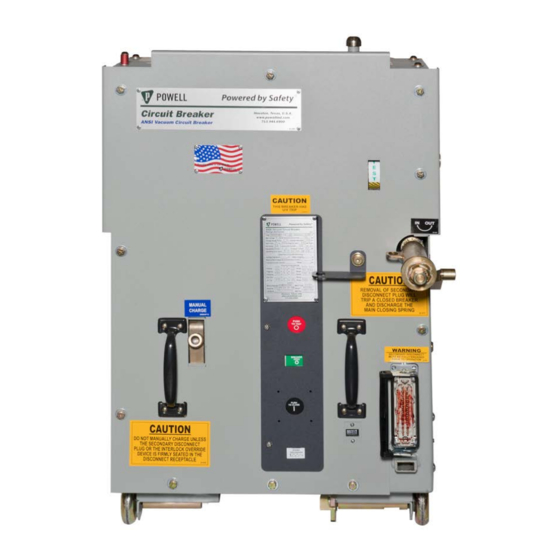
- Page 1 Powered by Safety ® 01.4IB.77000B PowlVac-ND® Vacuum Circuit Breaker 5kV / 1200A & 2000A / 36kA & 50kA...
- Page 2 PowlVac-ND® Vacuum Circuit Breaker 01.4IB.77000B Contact Information Powell Electrical Systems, Inc. powellind.com info@powellind.com Service Division PO Box 12818 Houston, Texas 77121-2818 713.944.6900 phone 713.948.4569 fax Powered by Safety Powered by Safety ® ®...
- Page 3 As stated in ANSI Z535.4-2007, the signal word is For the purposes of this manual, a qualified a word that calls attention to the safety sign and person, as stated in NFPA 70E®, is one who has designates a degree or level of hazard seriousness.
- Page 4 PowlVac-ND® Vacuum Circuit Breaker 01.4IB.77000B This page is intentionally left blank. Powered by Safety ®...
-
Page 5: Table Of Contents
B. p ................................2 urpoSe c. I ....................2 nStructIon ulletInS vAIlABle lectronIcAlly D. A ............................2 SSocIAteD ulletInS Ch 2 Safety ........................3 A. S ............................3 onDItIon B. S ...............................3 Afety uIDelIneS c. G ................................4 enerAl D. S ................................4 pecIfIc e. X-r ................................5... - Page 6 4) Secondary Shunt Trip Coil Assembly ..........................50 5) Undervoltage Device Assembly ............................50 6) Charging Motor Assembly ..............................50 7) Anti-Pump Relay Assembly ..............................50 8) Latch Check Switch ................................50 9) Motor Cutoff Switch Assembly ............................50 10) Auxiliary Switch ..................................50 Powered by Safety ®...
- Page 7 Table A Field Dielectric Test Values .................23 Table B Lubrication ......................37 Table C Timing .........................48 Table D Primary Resistance .....................48 Table E Primary Current Path ..................51 Table F Control Devices ....................52 Table G Miscellaneous Parts ...................54 Powered by Safety ®...
- Page 8 PowlVac-ND® Vacuum Circuit Breaker 01.4IB.77000B This page is intentionally left blank. Powered by Safety ®...
-
Page 9: Ch 1 General Information
Powell at 1.800.480.7273. NOTICE Powell reserves the right to discontinue and to change specifications at any time without incurring any obligation to incorporate new features in products previously sold. Powered by Safety ® General Information... -
Page 10: S Cope
01.4IB.51808A Vacuum Type Remote All illustrations and photos are shown using Racking Device (51897G29) deenergized equipment. WARNING Follow the appropriate safety precautions while handling any of the equipment. Failure to do so may result in death or serious injury. Powered by Safety ®... -
Page 11: Ch 2 Safety
OPEN or that drawout type circuit Furthermore, each user has the responsibility of breakers are withdrawn to the fully establishing a safety program for each type of disconnected position. equipment encountered. 4. Apply lockout/tagout devices in accordance with a documented and established policy. -
Page 12: G Eneral
If for and any adverse local conditions including any reason an interlock does not function excessive dust, ash, corrosive atmosphere, as described, do not make any adjustments, vermin and insect infestations. -
Page 13: X-R Ays
(3’) from the front of the circuit breaker. THE CIRCUIT BREAKER SHALL BE EITHER FULLY OPEN, OR FULLY CLOSED WHEN MAKING HIGH POTENTIAL TESTS. DO NOT TEST WITH CONTACTS PARTIALLY OPEN. Powered by Safety ® Safety... -
Page 14: Ch 3 Equipment Description
(Figure 1, ak). In rear of the circuit breaker frame prior to the same metal enclosed compartment as the installing the escutcheon. stored energy mechanism is the circuit breaker racking mechanism and interlocks which Powered by Safety ® Equipment Description... - Page 15 (Figure 2, h). The spring charge indicator (Figure 1, m) will display that the mechanism is charged. Powered by Safety ® Equipment Description...
-
Page 16: Figure 1 Powlvac-Nd Circuit Breaker - Exterior View
Lower Primary Disconnecting Device ai. Spring Yoke Manual Close Operator w. Frame aj. Contact Loading Spring Secondary Disconnect Receptacle Ground Connection ak. Operating Pushrod Operations Counter Serial Number Plate Location m. Spring Charge Indicator Wheel Powered by Safety ® Equipment Description... -
Page 17: Figure 2 Powlvac-Nd® Circuit Breaker - Interior View
Charging Motor aa. Holding Pawl Adjusting Eccentric Motor Cutoff Cam Pawl Lift Plate ab. Crank Arm Close Latch Arm Close Bar Adjusting Screw ac. Crank Pin Charging Motor Drive Shaft Drive Pawl ad. Closing Coil Powered by Safety ® Equipment Description... -
Page 18: Figure 3 Cam And Fundamental Linkage Positions
Figure 3 Cam and Fundamental Linkage Positions b) Breaker Closed - Spring Discharged a) Breaker Open - Spring Charged - Links Reset c) Breaker Open - Spring Discharged d) Breaker Closed - Spring Charged Powered by Safety ® Equipment Description... -
Page 19: Figure 4 Mechanism And Trip Linkages
Secondary Linkage Roller e. Main Cam Roller f. Reset Spring g. Camshaft h. Main Closing Cam Center Phase Operating Lever Jackshaft k. Primary Trip Prop Roller Primary Trip Prop Adjusting Screw m. Primary Trip Prop Powered by Safety ® Equipment Description... - Page 20 Further movement of the operating pushrod assembly compresses the contact loading spring even more and produces a gap between the face of the spring yoke and the lock nut. Powered by Safety ® Equipment Description...
-
Page 21: Figure 5 Operation Sequence
SET UP ENERGIZED RELEASE CLOSE MAKES BREAKS BREAKS MAKES CONTROL SWITCH "CS/C" BREAKS WHITE LIGHT MOTOR "M" ENERGIZED DE-ENERGIZED "Y" COIL DE-ENERGIZED "Y" CONTACT BREAKS PREVENTS PUMPING IF VCB TRIPS BEFORE CONTROL SWITCH IS RELEASED Powered by Safety ® Equipment Description... -
Page 22: Figure 6 Typical Ac/Dc Control Scheme
-- Charging Motor -- Breaker Auxiliary Contact (Normally Open) -- Breaker Auxiliary Contact (Normally Closed) -- Breaker Secondary Disconnect -- Normally Open -- Normally Closed -- Common RES -- Voltage Dropping Resistor (250VDC only) Powered by Safety ® Equipment Description... -
Page 23: Electrical Description
(Figure 2, w), operated inside the circuit breaker left frame side by a lever on the trip shaft, will close as the sheet, and is supported by two screws. secondary trip prop reaches the fully reset position. Powered by Safety ® Equipment Description... -
Page 24: Acking M Echanism
Into the The operation sequence for all control for more IrcuIt reAker oMpArtMent schemes is shown in Figure 5. Circuit information. breaker mounted auxiliary contacts not used in the control circuit are brought Powered by Safety ® Equipment Description... - Page 25 Powered by Safety ® Equipment Description...
-
Page 26: Closed Door Racking Mechanism
“CONN”. CAUTION Do not handle or move the circuit breaker by the primary disconnecting devices as damage may occur. Powered by Safety ® Equipment Description... -
Page 27: Secondary Disconnecting Devices
7) Anti-Rollout Latch To operate the anti-rollout latch (Figure 1, o), push the circuit breaker element forward in the compartment and depress the lever before pulling the circuit breaker element out of the compartment. Powered by Safety ® Equipment Description... -
Page 28: Acuum I Nterrupters
The sliding contact assembly inside the lower contact block makes contact with this block and the moving stem of the vacuum interrupter. The multiple parallel paths of the sliding contact assembly keeps the current density low. Powered by Safety ® Equipment Description... -
Page 29: Ch 4 Installation
The circuit breaker can also be lifted by an overhead crane using the two lifting holes which have been provided for hooks at the top of the circuit breaker frame side sheets (Figure 9). Powered by Safety ® Installation... -
Page 30: S Torage
Space heaters within the equipment should be energized, if so equipped. Humidity controlling desiccant materials should be utilized when space heaters are not provided or cannot be energized. The temperature should be kept above 33°F/1°C Powered by Safety ® Installation... -
Page 31: P Lacing The C Ircuit B Reaker I Nto S Ervice
DC testing is not the preferred method, however, values are provided due to the availability of DC test CAUTION sets. Remove all grounding conductors applied for this test before placing the circuit breaker back into service. Powered by Safety ® Installation... -
Page 32: Vacuum Integrity
25kVAC (35kVDC) determine “High voltage insulation integrity.” See Ch 4 Installation, for circuit breaker with a rated maximum D. p voltage of 4.76kV. lAcInG the IrcuIt reAker , 1) High Voltage Insulation ervIce Integrity. Powered by Safety ® Installation... -
Page 33: Control Voltage Insulation Integrity
DC leakage current. There is no significant correlation. CAUTION Remove all grounding conductors applied for this test before placing the circuit breaker back into service. Powered by Safety ® Installation... -
Page 34: Mechanical Operation Check
Lift the handle until it is horizontal and then depress. The procedure is repeated until the spring charge indicator indicates “CLOSING SPRING CHARGED”. This requires about 60 operations of the handle. Once the closing spring is charged, remove the handle. Powered by Safety ® Installation... -
Page 35: Electrical Operation Check
SCADA, or automatic transfer schemes. Powered by Safety ® Installation... -
Page 36: Racking Mechanism Check
NOTICE Be sure that the racking crank arms at the sides of the circuit breaker point in the direction of the primary disconnecting devices and the circuit breaker position indicator displays breaker test/disconnected. Powered by Safety ® Installation... -
Page 37: Prior To Inserting The Circuit Breaker Into The Circuit Breaker Compartment
Contact Powell for further information. Examine the circuit breaker compartment to see that it is clean and clear of debris that might interfere with circuit breaker travel. Powered by Safety ® Installation... -
Page 38: Inserting The Circuit Breaker To The Test/Disconnected Position
These illustrations may not be representative of site specific safety practices for performing arms make contact with the vertical slots in the compartment. The the procedure. Before attempting any racking anti-rollout latch under the circuit procedure, review Chapter 2. -
Page 39: Inserting The Circuit Breaker To The Connected Position
Once the shutters are open, the circuit breaker begins to move toward the stationary primary disconnecting devices. When the movable primary disconnecting devices of the circuit breaker engage with the stationary Powered by Safety ® Installation... -
Page 40: Emoving The
Prior to removing the circuit breaker from the circuit breaker compartment, make sure the circuit breaker is in the open position and all a. Breaker Position Indicator springs are discharged. b. Test Position c. Racking Mechanism Retainer Assembly Powered by Safety ® Installation... -
Page 41: C Ompartment
Racking Device for the proper operational door. procedure. b. Lift the secondary disconnect latch and remove the circuit breaker compartment’s secondary disconnect plug. Store the plug so it will not be damaged while withdrawing the circuit breaker. Powered by Safety ® Installation... -
Page 42: Ch 5 Maintenance
Ch 2 Safety With experience, each user can set an of this instruction bulletin. If there is any... -
Page 43: Inspection And Cleaning
Any damaged parts that will interfere with the normal operation of the circuit breaker should be replaced. This inspection will be much easier if the front cover and interphase barriers are removed. Powered by Safety ® Maintenance... -
Page 44: M Echanism A Rea
For further details see Ch 4 Installation, D. p lAcInG the IrcuIt reAker ervIce 4) Mechanical Operation Check & 6) Racking Mechanism Check. Powered by Safety ® Maintenance... - Page 45 Note: For all previous lubrication requirements Powlube-104 A-Grease replaces Anderol 757 and Rheolube 368A, B-Grease replaces Mobilgrease 28 and C-Oil replaces Mobil 1 and Anderol 456. See Ch 5 Maintenance, B. M , 2) Lubrication for more details. echAnISM Powered by Safety ® Maintenance...
-
Page 46: Figure 15 Lubrication
Motor Drive h. Pawls i. Close Latch Support Arm Shaft Roller Shaft Face Needle Bearings j. Ratchet Wheel k. Secondary l. Jackshaft m. Fundamental n. Racking Drive Disconnect Lever Pin Linkage Pin Shaft Extension Receptacle Powered by Safety ® Maintenance... -
Page 47: Figure 16 Lubrication (Cont)
Jackshaft u. Ground v. Motor Drive w. Wheel Outer Bearings Connection Shaft Coupling Support x. Motor Drive y. Camshaft z. Close Shaft aa. Motor Cutoff ab. Fundamental Shaft Support Needle Bearings Support Bearing Linkage Bearings Powered by Safety ® Maintenance... -
Page 48: Closing Spring Removal
Spacer and the main closing spring assembly can be removed. Note: Care should be taken on reassembly to ensure correct location of the flat washer, lock washer and spacer (Figure 18). Powered by Safety ® Maintenance... -
Page 49: Slow Closing Of Mechanism
5. While charging the main closing and toes out of the way, etc. springs, using the charging motor to drive the mechanism, observe the ratcheting operation for improvement. Powered by Safety ® Maintenance... -
Page 50: Figure 19 Primary & Secondary Trip Prop Adjustment
2. Loosen the secondary trip prop b. Primary Trip Prop Roller adjusting screw (Figure 21, c) locking c. Primary Trip Prop nut several full turns. d. Primary Trip Prop Adjusting Screw e. Rivet f. Trip Bar Powered by Safety ® Maintenance... -
Page 51: Figure 20 Feeler Gauge
(Figure 20). increments. This process may take several attempts. ii. If the circuit breaker did not TRIP during the test performed in step 11, reset the feeler gauges with 0.030” selected. Powered by Safety ® Maintenance... -
Page 52: Figure 21 Latch Check Switch Adjustment
3. Loosen the two screws which secure the latch check switch and rotate the latch check switch about the pivot screw downward to the lowest position allowed. The latch check switch contacts are now OPEN. Powered by Safety ® Maintenance... - Page 53 6. Turn the close bar adjusting screw 3 to 3½ full turns counterclockwise. Retighten the locking nut holding the screw. 7. Repeat step 5. Then CLOSE and OPEN the circuit breaker to ensure proper operation. 8. Replace the escutcheon. Powered by Safety ® Maintenance...
-
Page 54: Electrical Operation
Repeat the process for all 3 poles. a. Open Position Gap b. Bottom of Current Transfer Block c. Top of Operating Pin Powered by Safety ® Maintenance... -
Page 55: Sliding Contact Finger Wear
In these cases, interrupters. both the High Voltage Insulation Integrity and Control Voltage Insulation Integrity tests should be performed. For details of maintenance procedures, see Ch 4 Installation, D. p lAcInG the IrcuIt reAker ervIce Powered by Safety ® Maintenance... -
Page 56: Timing
Continuous Breaker Rated Resistance it is recommended after any major Current Type (kV) (Micro-ohms) (Amperes) maintenance that requires disassembly of any part of the primary current path. 05PV36MAX-21 1200 05PV36MAX-22 2000 05PV50MAX-21 1200 05PV50MAX-22 2000 Powered by Safety ® Maintenance... -
Page 57: Ch 6 Recommended Renewal Parts And Replacement Procedures
When continuous operation is a primary consideration, a larger quantity of renewal parts should be stocked depending on the severity of the service and the time required to secure replacement parts. Powered by Safety ® Recommended Renewal Parts and Replacement Procedures... -
Page 58: R Eplacement P Rocedures
Before attempting any maintenance repair replacement and installation procedures. work, take note of the safety practices outlined 5) Undervoltage Device Assembly in Ch 2 Safety of this instruction bulletin. Refer to service manual 01.4SM.1801 CAUTION Undervoltage Device for PowlVac-ND®... -
Page 59: Figure 24 Primary Current Path
05PV50SNDX 4.76 1200 77014G03P 77018G01P 77017G02P 05PV50SNDX 4.76 2000 77014G03P 77018G01P 77017G02P Figure 24 Primary Current Path a. Primary Disconnecting Device Assembly b. Vacuum Interrupter Assembly c. Operating Pushrod Assembly Powered by Safety ® Recommended Renewal Parts and Replacement Procedures... -
Page 60: Table F Control Devices
6) For use with capacitor trip units with 240VAC input. Consult factory for other circuit breaker ratings. 7) All control devices are available with push-on terminals. Consult factory for control devices with screw terminals. Powered by Safety ® Recommended Renewal Parts and Replacement Procedures... -
Page 61: Figure 25 Control Devices
Control Devices a. Primary Shunt Trip Coil (3 cycle) b. Primary Shunt Trip Coil (5 cycle) c. Charging Motor Assembly d. Closing Coil Assembly e. Anti-Pump Relay f. Undervoltage Device Assembly Powered by Safety ® Recommended Renewal Parts and Replacement Procedures... -
Page 62: Table G Miscellaneous Parts
Screw Terminals 102108LP Ground Connection 69433G01 Latch Check Switch BA-2RV2-A2 Motor Cutoff Switch Assembly 77034G01P PowlVac-ND® Hardware Kit 60500G24 PowlVac-ND® Lubrication Powlube-104 Operating Pushrod Assembly 5kV 36kA 77017G01 5kV 50kA 77017G02 Powered by Safety ® Recommended Renewal Parts and Replacement Procedures... - Page 63 01.4IB.77000B PowlVac-ND® Vacuum Circuit Breaker 1200A & 2000A 36kA & 50kA July 2015 Powered by Safety ® Powell Electrical Systems, Inc. Tel: 713.944.6900 • Fax: 713.948.4569 Service Division - Houston powellind.com PO Box 12818 • Houston, TX • 77217 info@powellind.com...
Need help?
Do you have a question about the POWELL PowlVac-ND and is the answer not in the manual?
Questions and answers