Table of Contents
Advertisement
Quick Links
INSTALLATION MANUAL
AIR
CONDITIONER
Please read this installation manual completely before installing the product.
Installation work must be performed in accordance with the national wiring
standards by authorized personnel only.
Please retain this installation manual for future reference after reading it thoroughly.
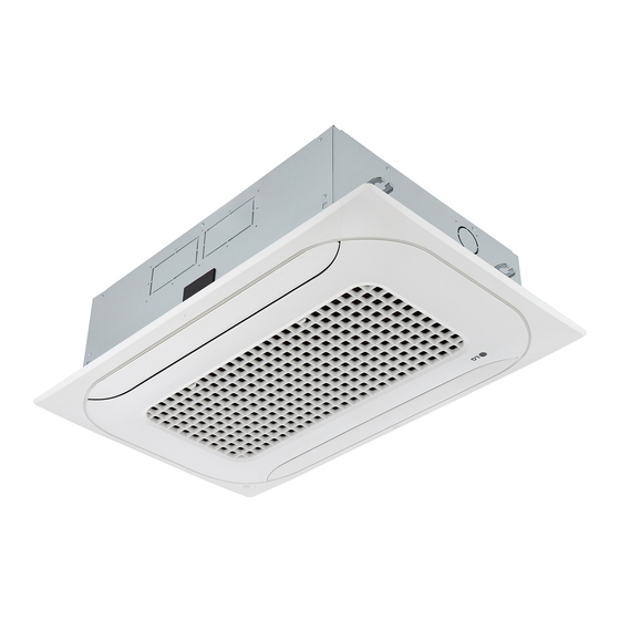
Ceiling Cassette – 2Way
ARNU09GTSA4 ARNU12GTSA4 ARNU18GTSA4 ARNU24GTSA4
Original instruction
MFL68686533
Rev.00_040519
Copyright © 2018 - 2019 LG Electronics Inc. All Rights Reserved.
www.lg.com
Advertisement
Table of Contents

Related Manuals for LG ARNU09GTSA4


Summary of Contents for LG ARNU09GTSA4
- Page 1 Please retain this installation manual for future reference after reading it thoroughly. Ceiling Cassette – 2Way ARNU09GTSA4 ARNU12GTSA4 ARNU18GTSA4 ARNU24GTSA4 Original instruction www.lg.com MFL68686533 Rev.00_040519 Copyright © 2018 - 2019 LG Electronics Inc. All Rights Reserved.
-
Page 2: Table Of Contents
Table of contents TABLE OF CONTENTS INSTALLATION PARTS SAFETY PRECAUTIONS INSTALLATION Model Designation Airborne Noise Emission Limiting concentration Selection of the best location Ceiling dimension and hanging bolt location Wiring Connection Installation of Decoration Panel Drain Piping DIP Switch Setting Group Control Setting Indoor Unit... -
Page 3: Installation Parts
Installation Parts Installation Parts Air filter Air Intake Air Outlet Wired Remote Controller (Optional) Installation Tool Washer for Clamp Insulation for Name Drain hose Clamp metal (Other) hanging bracket (Tie Wrap) fitting Quantity 1 EA 2 EA 8 set 4 EA 1 EA •... -
Page 4: Safety Precautions
Safety Precautions Safety Precautions To prevent injury to the user or other people and property damage, the following instructions must be followed. n Be sure to read before installing the air conditioner. n Be sure to observe the cautions specified here as they include important items related to safety. n Incorrect operation due to ignoring instruction will cause harm or damage. - Page 5 Safety Precautions • Be sure the installation area does not deteriorate with age. - If the base collapses, the air conditioner could fall with it, causing property damage, product failure, and personal injury. • Use a vacuum pump or inert (nitrogen) gas when doing leakage test or air purge. Do not compress air or oxygen, and do not use flammable gases.
-
Page 6: Installation
Installation Installation Read completely, then follow step by step. Model Designation Serial Number Combinations of functions A:Basic function C: Ionizer(Ceiling Cassette) : Optional Chassis Name Electrical Ratings 3:1 Ø, 208/230 V, 60 Hz G:1 Ø, 220 - 240 V, 50 Hz/1 Ø, 220 V, 60 Hz (Only 50 Hz for Australia) Total Cooling Capacity in Btu/h EX) 5 000 Btu/h ➝... -
Page 7: Selection Of The Best Location
Installation Selection of the best location • There should not be any heat source or steam near the unit. • There should not be any obstacles to the air circulation. • A place where air circulation in the room will be good. •... -
Page 8: Ceiling Dimension And Hanging Bolt Location
Installation Ceiling dimension and hanging bolt location • The dimensions of the paper model for installation are the same as those of the ceiling opening dimensions. 1 033 (Ceiling opening) 855 (Hanging bolt) Ceiling Level gauge CAUTION • This air-conditioner uses a drain pump. •... -
Page 9: Wiring Connection
Installation Ceiling Keep the length of the bolt Hanging bolt from the bracket to 40 mm (W3/8 or M10) Flat washer for M10 (W3/8 or M10) Air Conditioner body (accessory) Ceiling board Ceiling board Ceiling board Ceiling board Flat washer for M10 (accessory) Paper pattern Set screw of... -
Page 10: Installation Of Decoration Panel
Installation Installation of Decoration Panel The decoration panel has its Before installing the decoration panel, installation direction. always remove the paper template. 1. Temporarily fix two decoration panel fixing screws (hexagon M5 screw) on the unit body. (Tighten by amount 10 mm in length.) The fixing screws (hexagon M5 screw) are included the indoor unit box. -
Page 11: Drain Piping
Installation Drain Piping • Drain piping must have down-slope (1/50 to Upward 1/100): be sure not to provide up-and-down slope Pipe clamp routing to prevent reversal flow. not allowed • During drain piping connection, be careful not to Indoor unit exert extra force on the drain port on the indoor unit. - Page 12 Installation CAUTION Be sure to test the power line and communication line for incorrect wiring before power is applied. 1) If the power line and communication line are swapped over, the product will be damaged. 2) Incorrect wiring confirmation test method : Measure the resistance across the power terminals (L, N) using a multi meter.
-
Page 13: Dip Switch Setting
Installation DIP Switch Setting 1. Indoor Unit Function Description Setting Off Setting On Default Communication N/A (Default) Cycle N/A (Default) Selection of Master or Group Control Master Slave Slave Wired/Wireless remote Dry Contact Selection of Dry controller selection of Auto Mode Contact Mode Manual or Auto... -
Page 14: Group Control Setting
Installation Group Control Setting 1. Group Control 1 n Wired remote controller 1 + Standard Indoor Units LGAP Network System Signal Master Slave Slave Slave 12 V Display Error Message Only connect serial signal and GND lines between indoor units. Master °C / °F (5 s) °C / °F (5 s) - Page 15 Installation h It is possible to connect indoor units since Feb. 2009. h It can be the cause of malfuctions when there is no setting of master and slave. h In case of Group Control, it is possible to use following functions. - Selection of operation, stop or mode - Temperature setting and room temperature check - Current time change...
- Page 16 Installation 3. Group Control 3 n Mixture connection with indoor units and Fresh Air Intake Unit LGAP Network System Signal Master Slave Master Slave 12 V Display Error Message Display Error Message °C / °F (5 s) °C / °F (5 s) TIME (3 s) TIME (3 s) Master...
- Page 17 Installation 4. 2 Remote Control n Wired remote controller 2 + Indoor unit 1 LGAP Network System Slave Slave Signal Slave Master 12 V Display Error Message °C / °F (5 s) °C / °F (5 s) TIME (3 s) TIME (3 s) Master Slave...
- Page 18 Installation 5. Accessories for group control setting It is possible to set group control by using below accessories. Indoor unit 2 EA +Wired remote controller 1 EA Indoor unit 1 EA +Wired remote controller 2 EA h PZCWRCG3 cable used for connection h PZCWRC2 cable used for connection Slave Master...
- Page 19 PT.LG Electronics Indonesia Gandaria 8 Office Tower Lt. 29 BC & 31 ABCD Jl.Sultan Iskandar Muda, Kebayoran Lama Utara - Kebayoran Lama, Jakarta Selatan - DKI Jakarta Raya, Indonesia...
Need help?
Do you have a question about the ARNU09GTSA4 and is the answer not in the manual?
Questions and answers