Table of Contents
Advertisement
Quick Links
OPERATING MANUAL
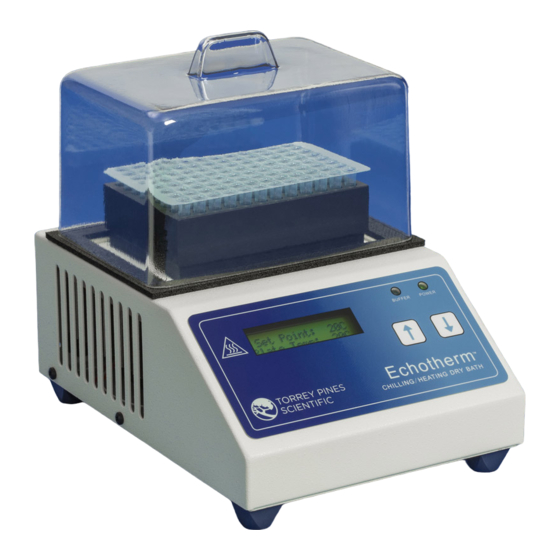
EchoTherm
DIGITAL, ELECTRONIC CHILLING/HEATING DRY BATH
MODELS IC25, XT, XR and IC35, XT
Applies to versions 5.7 and higher
DOCUMENT NUMBER IC25-100
Revised Feb 2021
TORREY PINES SCIENTIFIC, INC.
2713 Loker Ave. West
Carlsbad, CA 92010
TELEPHONE: (760)-930-9400
TOLL FREE: (866)-573-9104
FAX: (760)-930-9480
E-Mail: info@torreypinesscientific.com
Web site:
www.torreypinesscientific.com
Advertisement
Table of Contents

Subscribe to Our Youtube Channel
Related Manuals for TORREY PINES SCIENTIFIC EchoTherm IC25


Summary of Contents for TORREY PINES SCIENTIFIC EchoTherm IC25
- Page 1 DIGITAL, ELECTRONIC CHILLING/HEATING DRY BATH MODELS IC25, XT, XR and IC35, XT Applies to versions 5.7 and higher DOCUMENT NUMBER IC25-100 Revised Feb 2021 TORREY PINES SCIENTIFIC, INC. 2713 Loker Ave. West Carlsbad, CA 92010 TELEPHONE: (760)-930-9400 TOLL FREE: (866)-573-9104 FAX: (760)-930-9480 E-Mail: info@torreypinesscientific.com...
-
Page 2: Table Of Contents
PUSH BUTTONS ..................12 X. SETTING TEMPERATURE AND OTHER FEATURES ......... 13 SETTING TEMPERATURE ................13 SETTING TIMER ..................13 SETTING THE UNIT TO “IDLE MODE” ............16 DATA LOGGER .................... 18 XI. PROGRAMMING ................... 20 Torrey Pines Scientific, Inc. - Page 3 XV. CLEANING, MAINTENANCE, AND CONSUMABLE PARTS ..... 33 CLEANING ....................33 MAINTENANCE .................... 33 SPARE PARTS AND CONSUMABLES ............34 XVI. ADDITIONAL SYMBOLS ................34 APPENDIX A: Example Programming Scenarios ........... 35 APPENDIX B: Commands Using the Serial Port ..........38 Torrey Pines Scientific, Inc.
-
Page 4: Introduction
II. WARRANTY Torrey Pines Scientific warrants this product to be free from defects in material and workmanship for a period of one year from the date of purchase. If repair or adjustment is necessary and has not been the result of abuse or misuse within the one year period, please return---freight prepaid---and correction of the defect will be made without charge. -
Page 5: Labels
AC input cord for the power supply. Be certain to use a line cord with the same rating and of the same type as the one supplied by the manufacturer. Use the normal care and precaution one would use with any electrical appliance. Torrey Pines Scientific, Inc. -
Page 6: General Description
VI. GENERAL DESCRIPTION Torrey Pines Scientific IC25/35 units are Peltier driven for chilling & heating. They come with a universal power supply and the chilling/heating module. The units have only one moving part, the DC fan that cools the unit. Everything else is solid state and should last years without problem. -
Page 7: Data Logger
MENU options, user changed calibration points, logged data points, and all programmed sequence values. The stored values will be recalled each time the unit powers up to maintain the configuration of the previous session. Torrey Pines Scientific, Inc. -
Page 8: Front And Rear Panel Controls
There are two LEDs on the front panel. One is a power-on indicator and the other is the plate surface hot indicator that will illuminate when the plate is at or above 50C. Torrey Pines Scientific, Inc. -
Page 9: Rear Panel
REAR PANEL The rear panel shown has the on/off power switch at the left, the 12 volt dc power input jack in the middle, the DB9 connector for the RS232 I/O port is on the right. Torrey Pines Scientific, Inc. -
Page 10: Set Up Parameters
6. Set target temperature and timer, if wanted, according to the instructions that follow. Note: Do not use this equipment in any manner not specified by the manufacturer. ENVIRONMENTAL INFORMATION 1. This unit is for installation category II. 2. This unit is rated pollution degree 2. Torrey Pines Scientific, Inc. -
Page 11: Display And Keyboard Descriptions
The two push buttons enable the user to set a temperature, to set a timer, and to calibrate the temperature against a local standard. Figure 1 below describes the screens for several modes of operation. Figure 1: Display Screens for Different Modes of Operation Torrey Pines Scientific, Inc. -
Page 12: Push Buttons
Menu on the LCD display. Scrolling to the various options in the Menu is accomplished by pressing the UP and DOWN ARROW buttons. This manual contains details on accessing and setting the various Menu options. Torrey Pines Scientific, Inc. -
Page 13: Setting Temperature And Other Features
If the “Auto-Off” feature is disabled (“Auto-Off: no”), the unit will continue to control the plate to the set point temperature when the timer reaches zero. If the “Auto-Off” feature is enabled (“Auto- Torrey Pines Scientific, Inc. - Page 14 Idle Mode, no power will be directed to the plate—the plate is essentially “turned off” and will naturally return to room temperature. See the Idle Mode section of this manual for more details. Figure 2: Menu Map to Set and Start the Timer Torrey Pines Scientific, Inc.
- Page 15 Figure 3: Menu Map to Stop the Running Timer Figure 4: Menu Map to Select Timer Options Torrey Pines Scientific, Inc.
-
Page 16: Setting The Unit To "Idle Mode
1. By pressing either arrow button –the set point will be set to 20C. 2. By selecting “Clr Idle Mode” from the menu—the set point before the unit was set to Idle Mode will be restored Figure 5: Menu Map to Set Idle Mode Using the Menu Torrey Pines Scientific, Inc. - Page 17 Figure 6: Menu Map to Clear Idle Mode Using the Menu Torrey Pines Scientific, Inc.
-
Page 18: Data Logger
RS232 I/O port (ref XIV. RS232 INTERFACE). Figures 7, 8, and 9 show the steps to set the log period and how to start and stop a logging session. Figure 7: Menu Map to Set Log Period Torrey Pines Scientific, Inc. - Page 19 Figure 8: Menu Map to Start Logging Session Figure 9: Menu Map to Stop Logging Session Torrey Pines Scientific, Inc.
-
Page 20: Programming
(1-99 cycles or infinite) then start the program. The following sections describe the keystrokes and other programming details. See Appendix A for examples of defined the program steps and the effects of using the global Program Option and Timer Option settings. Torrey Pines Scientific, Inc. -
Page 21: Menu: Program
10 steps per sequence. The “Program” Menu option provides the ability to choose a program to run or to edit. Figure 10 below shows the menu map for the Program feature. Figure 10: Menu Map For Program Control Torrey Pines Scientific, Inc. -
Page 22: Menu: Program >Edit
LCD in the Program >Edit mode. See Appendix A for examples of defined the program steps and the effects of using the global Program Option and Timer Option settings. Figure 11: Description of Items in Program >Edit Screen Torrey Pines Scientific, Inc. - Page 23 Figure 12 below shows the keystrokes required to set the values for each step parameter and how to navigate from one step to the next. Figure 12: Menu Map For Defining or Editing Program Steps Torrey Pines Scientific, Inc.
-
Page 24: Menu: Program >Run
Figure 13 below provides a description of the steps and keystrokes required to define the program cycles and to start the program running. Figure 13: Menu Map For Setting Program Cycles and Running Program Torrey Pines Scientific, Inc. - Page 25 Figure 14 below provides a description of the LCD screen when a program is running. Figure 14: Description of the Display While a Program is Running Torrey Pines Scientific, Inc.
-
Page 26: Menu: Pgm Options
See Appendix A for examples of defined the program steps and the effects of using the global Program Option and Timer Option settings. Figure 15: Menu Map For Setting the “Timer Waits” Program Option Torrey Pines Scientific, Inc. -
Page 27: Temperature Calibration
Two-Point User Calibration Proper two-point calibration requires the unit to be calibrated by the user at both a low temperature and a high temperature. After calibration, the control algorithm inside the IC25 Torrey Pines Scientific, Inc. -
Page 28: Single-Point User Calibration
37C, the measured value when the unit reads 37C will be 37C, but when the unit reads 25C the measured value will likely be higher or lower than 25C. * “IC25” in the above text applies to models IC25 and IC35, STD, XT, and XR Torrey Pines Scientific, Inc. -
Page 29: Menu: Calibrate
Check with the factory if help is needed. Also, calibration kits are available. Figure 16: Menu Map to Calibrate the Plate Temperatures Torrey Pines Scientific, Inc. -
Page 30: Menu: Reset Cal Points
“Set to Factory” and the unit will retrieve the calibration values obtained when the unit was calibrated at the factory prior to shipment. Selecting “Set to Not Cal” will remove all calibration corrections and the unit will be “uncalibrated”. Figure 17: Menu Map to Reset Calibration Points Torrey Pines Scientific, Inc. -
Page 31: Temperature Measurement Error Codes
Recommended Action The RTD Sensor is not connected or has RTDo Inspect Sensor and Sensor Connector failed and/or Contact Torrey Pines Scientific RTDs The RTD Sensor has shorted or has failed The Calibrated Temperature Value is out cal0 of range... -
Page 32: Rs232 Serial Com Interface
9600 baud 1 stop bit no parity no hardware handshake 100ms delay after each command sent (after \r) Note: To comply with CE and to avoid possible EMI radiation from the RS232 cable, use a shielded cable. Torrey Pines Scientific, Inc. -
Page 33: Cleaning, Maintenance, And Consumable Parts
UP or the DOWN Arrow buttons. Three dots (“---“) should appear on the LCD display—continue pressing the button until the message “Unit Reset” appears on the LCD display. Torrey Pines Scientific, Inc. -
Page 34: Spare Parts And Consumables
Power Cord, Germany (European) 730-0003 Power Cord, UK 730-0004 Power Cord, Italy 730-0005 Power Cord, Australia/China XVI. ADDITIONAL SYMBOLS The following are additional symbols found on labels on the instrument Symbol Description Voltage Alternating Current Current Frequency Power Torrey Pines Scientific, Inc. -
Page 35: Appendix A: Example Programming Scenarios
Using the appropriate combination of global settings and step settings offers flexibility in defining the behavior of a program both running and upon completion. The following examples are provided to illustrate the settings for four sample programming scenarios Torrey Pines Scientific, Inc. - Page 36 IC25/35 front panel to return to the default screen. In this example, the unit continues operation at the same set point as the last programmed step. Torrey Pines Scientific, Inc.
- Page 37 The timer will continue to count up from the end of step 3 until the user presses a button on the front panel. Additionally, the user must use the Menu to Exit Idle Mode to enable setting a new set point temperature. Torrey Pines Scientific, Inc.
-
Page 38: Appendix B: Commands Using The Serial Port
“yes”, all steps in a running program will wait until the step set point is reached before the timer decrements and vice versa. It is not possible to program a sequence where some steps are “wait until” and some are not. APPENDIX B: Commands Using the Serial Port Torrey Pines Scientific, Inc. - Page 39 Description: When the command V<CR> is received by the IC20/25 unit, the 8 character serial number will be returned in a text string terminated by <CR><LF>. The serial number for every IC20/25 unit is unique. If the command is not received in the proper syntax, e<CR><LF> will be returned. Torrey Pines Scientific, Inc.
- Page 40 Example1— Change set point to -10C: send: n-10<CR> returned: ok <CR><LF> Example2 – Change set point to 9C : send: n9<CR> returned: ok <CR><LF> Example3 – Change set point to 100C : send: n100<CR> returned: ok <CR><LF> Torrey Pines Scientific, Inc.
- Page 41 If the command is not received in the proper syntax, e<CR><LF> will be returned. See Command: #F or Figure 17 to reset cal points if a calibration error has occurred Example—Return the plate temperature: send: p<CR> returned example 1: -10 <CR><LF> returned example 2: 9 <CR><LF> Torrey Pines Scientific, Inc.
- Page 42 Description: When the command le<CR> is received by the IC20/25 unit, the unit will set the logging period to 1 second which means that a data point will be stored once every second. If the command is not received in the proper syntax, e<CR><LF> will be returned. Torrey Pines Scientific, Inc.
- Page 43 Description: When the command #F<CR> is received by the IC20/25 unit, the unit will reset and store all calibration values to those measured and set in the factory prior to shipment. Example – reset cal vals back to factory send: #F<CR> Torrey Pines Scientific, Inc.
- Page 44 Function: Reset Unit to Default Configuration Description: When the command #Z<CR> is received by the IC20/25 unit, the unit will reset all non-volatile memory to default factory values. Example – reset Unit send: #Z<CR> returned: Unit Reset<CR><LF> Torrey Pines Scientific, Inc.
- Page 45 Reset unit to default configuration (rarely necessary) #Z<CR> Uint Reset <CR LF> <CR> is ASCII eturn char (for example: “enter” keyboard press for HyperTerminal, “\r” for C pgms, ASCII hex char “D”) <LF> is ASCII linefeed char (d’10 or ‘\n’) Torrey Pines Scientific, Inc.
Need help?
Do you have a question about the EchoTherm IC25 and is the answer not in the manual?
Questions and answers