Table of Contents
Advertisement
Available languages
Available languages
Quick Links
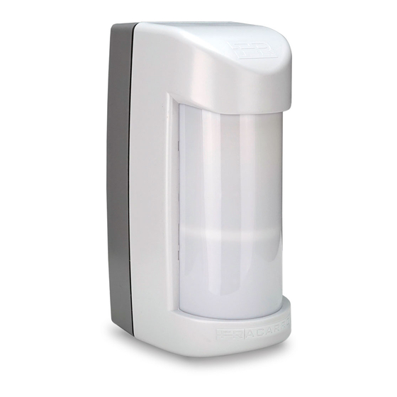
SHIELD V
(998993)
ITA: Rivelatore Volumetrico da Esterno Tripla Tecnologia con
Funzione Antiaccecamento
EN: Outdoor Volumetric Detector, Triple Technology with
Anti-Masking Function
FRA: Détecteur Volumétrique extérieur, triple technologie avec
fonction Anti-masquage
ITA: ISTRUZIONI PER L'USO (pag. 2 - 12)
EN: OPERATING INSTRUCTIONS (pag. 13 - 23)
FRA: MODE D'EMPLOI (pag. 24 - 34)
1
Advertisement
Table of Contents

Related Manuals for Fracarro SHIELD V


Summary of Contents for Fracarro SHIELD V
- Page 1 SHIELD V (998993) ITA: Rivelatore Volumetrico da Esterno Tripla Tecnologia con Funzione Antiaccecamento EN: Outdoor Volumetric Detector, Triple Technology with Anti-Masking Function FRA: Détecteur Volumétrique extérieur, triple technologie avec fonction Anti-masquage ITA: ISTRUZIONI PER L’USO (pag. 2 - 12) EN: OPERATING INSTRUCTIONS (pag. 13 - 23)
-
Page 2: Avvertenze Per La Sicurezza
In caso di guasto non tentate di riparare il prodotto altrimenti la garanzia non sarà più valida. Le informazioni riportate in questo manuale sono state compilate con cura, tuttavia Fracarro Radioindustrie S.r.l. si riserva il diritto di apportare in ogni momento e senza preavviso, miglioramenti e/o modifiche ai prodotti descritti nel presente manuale. -
Page 3: Specifiche Tecniche
3. SPECIFICHE TECNICHE Alimentazione da 9 a 15 Vcc Consumo a 12 Vcc 20 mA (max.) Frequenza microonda Banda K 24GHz Contatti di allarme mascheramento MOS FET relay 100 mA 35 V, 2 Ω max. Copertura rilevazione 3 ~ 18 mt Tempo di allarme Antimascheramento IR attivi... -
Page 4: Installazione Del Prodotto
4. INSTALLAZIONE DEL PRODOTTO IDENTIFICAZIONE DELLE PARTI Part. Identificazione Viti di fissaggio del supporto rilevatore sulla staffa fissaggio a parete. Vite di fissaggio del coperchio. Coperchio con lente di Fresnel. Pomello di regolazione PIR2 basso. Elettronica e supporto con possibilità di rotazione di 150°. Microinterruttore con funzione antistrappo (solo se fissato con la vite A). - Page 5 INSTALLAZIONE AVVERTENZE GENERALI Prima dell'installazione verificare le seguenti condizioni: • la parete non deve presentare avvallamenti o sporgenze eccessive; • installare il rilevatore su superfici rigide prive di vibrazioni; • evitare il posizionamento del rilevatore vicino a fonti di calore o alla luce diretta del sole; •...
- Page 6 FIG. 6 - Poggiare il corpo del rilevatore sulla staffa e farlo scendere fino in fondo per far coincidere i fori di fissaggio del corpo con quelli della staffa Per ottenere il passaggio cavo, forare l’apposito pre taglio utilizzando un oggetto appuntito di adeguato diametro, giravite o simile.
-
Page 7: Collegamenti Elettrici
MONTAGGIO NON CORRETTO Accertarsi che il rilevatore sia montato perpendicolarmente rispetto al terreno. Fig. 11 Il rilevatore è equipaggiato con speciali filtri per i disturbi dei raggi solari; nei limiti del possibile è comunque consigliata l’installazione evitando il sole diretto. Fig. - Page 8 Antimascheramento Il rilevatore è dotato di antimascheramento a infrarossi attivi per la protezione dei sensori piroelettrici, che genera un segnale di manomissione entro 3 minuti. L’uscita dedicata a questa funzione è il morsetto denominato MASK (v. fig. 13). In una installazione tipica questo morsetto può essere collegato ad una linea attiva 24h o ad un ingresso di centrale opportuna- mente programmato per l’invio di messaggi di anomalia.
- Page 9 Fig. 18 Fig. 19 Fig. 20 Se l’oggetto in movimento risulta essere particolarmente grande (per esempio un’automobile) c’è la possibilità che il rilevatore possa rilevarne la presenza anche a distanze maggiori di 18 m. Quando si imposta la funzionalità del rilevatore in triplo AND (Dip 3 e 4 in OFF) la distanza che si ottiene tramite la regolazione del PIR 2 (basso) è...
-
Page 10: Funzionamento
Regolazione portata microonda Fig. 21 Si raccomanda di diminuire la sensibilità della microonda in rapporto alla distanza di copertura desiderata. IMPOSTAZIONE DIP SWITCH DIP 1 DIP 2 DESCRIZIONE FUNZIONAMENTO PIR 1 / PIR 2: sensibilità ALTA. PIR 1 / PIR 2: sensibilità MEDIO-ALTA. PIR 1 / PIR 2: sensibilità... - Page 11 Funzionamento in AND Esempio di rilevamento in modalità triplo AND (dip 3 e 4 in OFF) ( 1 ) NO ALARM L’animale viene rilevato da due delle tre tecnologie (PIR basso e MW) per cui l’allarme NON si attiva. Fig. 22 ( 2 ) NO ALARM La persona viene rilevata da due delle tre tecnologie (PIR alto e MW) per cui l’allarme NON si attiva.
-
Page 12: Manutenzione E Verifiche Periodiche
RICERCA DEI GUASTI E/O MALFUNZIONAMENTI PROBLEMA SOLUZIONE I LED non si accendono Verificare la correttezza dei collegamenti Verificare la presenza ed il valore dell’alimentazione Verificare che il Dip Switch 6 sia in posizione OFF Falsi allarmi Il rilevatore non è perpendicolare al terreno Il PIR basso è... -
Page 13: Safety Warnings
COMPLIANCE WITH EUROPEAN DIRECTIVES Fracarro declares that the product complies with the 2014/53 / EU and 2011/65 / EU directives. The full text of the EU declaration of conformity is available at the following internet address ce.fracarro.com 2. -
Page 14: Technical Specifications
3. TECHNICAL SPECIFICATIONS TECHNICAL FEATURES SHIELD V from 9 to 15 Vcc Power supply Current consumption @ 12Vcc 20 mA (max.) Microwave frequency K Band 24GHz Alarm, masking contacts MOS FET relay 100 mA 35 V, 2 Ω max. Motion detection coverage... -
Page 15: Installing The Product
4. INSTALLING THE PRODUCT PARTS IDENTIFICATION Table 1 Part. Identification Detector on wall fixing screws. Cover fixing screw. Cover with Fresnel lens. Adjusting knob for lower PIR2. Electronics and support, with possibility of rotation of 150 °. Antitamper micro switch (only if fixed with screw A). Stainless steel wall fixing bracket. -
Page 16: Mounting The Detector
NSTALLATION GENERAL PRECAUTIONS Before starting the installation, make sure that: • the wall does not have any pronounced depressions or protrusions; • install the detector on rigid surfaces, free of vibrations; • avoid to fix the detectors near to heat sources or at direct sunlight; •... -
Page 17: Correct Installation
FIG. 6 - Locate the detector body on the metallic support and slide It down, then fix it using the supplied screws. In order to obtain a passage for the cables, break the plastic pre-cut using a pointed object of appropriate diameter, screwdriver or similar. -
Page 18: Electrical Wiring
WRONG INSTALLATION Take care to install the detector perpendicularly to the ground. Fig. 11 The detector is equipped with special filters for solar radiation disturbances; as far as possible, installation is recommended, avoiding direct sunlight. Fig. 12 ELECTRICAL WIRING POWER: Power 12 Vdc (10 ~ 15 Vdc) MASK: Anti-mask output: normally closed contact in standby. - Page 19 Anti-masking The detector is equipped with an active IR anti-masking function to protect the pyroelectric sensors. It emits a tampering signal within 3 minutes. The output of this function is the MASK terminal block (see fig. 13). In a standard configuration, this terminal block can be connected to a 24h active line or to a control unit input appropriately programmed to send fault messages.
- Page 20 Fig. 18 Fig. 19 Fig. 20 If the object in motion is very large (for example a car) there is possibility that the detector can detect its presence even if it’s farther than 18 m. If the detector is set in triple AND (Dip 3 and 4 in OFF position) configuration, the maximum distance of detection is the one setted through the Adjustment of the PIR2.
-
Page 21: Dip Switch Setting
Microwave flow regulation Fig. 21 It is recommended to reduce the sensitivity of the microwave in relation to the desired coverage distance. DIP SWITCH SETTING DIP 1 DIP 2 FUNCTIONAL DESCRIPTION PIR 1 / PIR 2: HIGH sensitivity. PIR 1 / PIR 2: MEDIUM-HIGH sensitivity. PIR 1 / PIR 2: MEDIUM-LOW sensitivity. - Page 22 Operation in AND mode Example of detection in triple AND mode (dip 3 and 4 in OFF) ( 1 ) NO ALARM The animal is detected by two of the three technologies (low PIR and MW) for which the alarm is NOT activated. Fig.
-
Page 23: Troubleshooting
TROUBLESHOOTING PROBLEM SOLUTION LEDs do not light up Verify the correctness of the connections Check the presence and value of the power supply Verify that the Dip Switch 6 is in the OFF position False alarms The detector is not perpendicular to the ground The lower PIR is poorly regulated, reaching distances greater than desired Moving objects in the protected area (flat linen, tree branches) The MW sensitivity trimmer is at most... -
Page 24: Avertissements De Sécurité
CONFORMITÉ AUX DIRECTIVES EUROPÉENNES Fracarro déclare que le produit est conforme aux directives 2014/53 / EU et 2011/65 / EU. Le texte intégral de la déclaration de conformité UE est disponible à l'adresse internet suivante ce.fracarro.com 2. DESCRIPTION DU PRODUIT DESCRIPTION Le détecteur extérieur se compose de deux capteurs passifs doubles PIR et d'un micro-ondes 24 GHz. -
Page 25: Spécifications Techniques
3. SPÉCIFICATIONS TECHNIQUES CARACTÉRISTIQUES SHIELD V TECHNIQUES Alimentation de 9 à 15 Vcc. Consommation @ 12Vcc 20 mA (max.) Fréquence micro-ondes K bande 24GHz Contact de l'alarme de masquage MOS FET relay 100 mA 35 V, 2 Ω max. Couverture de détection 3 ~ 18 mt Durée de l'alarme... -
Page 26: Installation Du Produit
4. INSTALLATION DU PRODUIT Tableau 1 Part. Identification Vis de fixation du support du détecteur sur le support de fixation murale. Vis de fixation du couvercle. Couvercle avec lentille de Fresnel. Bouton de réglage pour PIR2 inférieur. Electronique et support avec possibilité de rotation de 150 °. Microinterrupteur avec fonction anti-sabotage (uniquement si fixé... -
Page 27: Montage Du Détecteur
STALLATION AVERTISSEMENTS GÉNÉRAUX Avant l'installation, vérifiez les conditions suivantes: • le mur ne doit pas présenter de dépressions ou de saillies excessives; • installer le détecteur sur des surfaces rigides sans vibrations; • éviter de placer le détecteur à proximité de sources de chaleur ou à la lumière directe du soleil; •... - Page 28 FIG. 6 - Placez le corps du détecteur sur le support et laissez-le descendre vers le bas pour faire correspondre les trous de fixation du corps avec ceux du support Pour obtenir le passage du câble, percer la prédécoupe appropriée à l'aide d'un objet pointu de diamètre approprié, tournevis ou similaire.
-
Page 29: Câblage Électrique
INSTALLATION INCORRECTE Assurez-vous que le détecteur est monté perpendiculairement au sol. Fig. 11 Le détecteur est équipé de filtres spéciaux pour les perturbations du rayonnement solaire; dans la mesure du possible, il est recommandée de réaliser l'installation, en évitant la lumière directe du soleil. Fig. - Page 30 Anti-masquage Le détecteur est équipé d'une fonction anti-masquage IR active pour protéger les capteurs pyroélectriques. Il émet un signal de sabotage dans les 3 minutes. La sortie de cette fonction est le bornier MASK (voir la figure 13). Dans une configuration standard, ce bornier peut être connecté à une ligne active 24h ou à une entrée de l'unité de contrôle programmée de façon appropriée pour envoyer des messages d'erreur.
- Page 31 Fig. 18 Fig. 19 Fig. 20 Si l'objet en mouvent est très grand (par ex. une voiture) il est possible que le dispositif détecte sa présence même à une distance supérieure à 18m. Si le dipositif est réglé enconfiguration triple AND (Dip 3 et 4 en position OFF), la distance maximum de détection est celle obtenue par le réglage du PIR2 (inférieur).
-
Page 32: Description Fonctionnelle
Réglage de la portée du micro-onde Fig. 21 Il est recommandé de réduire la sensibilité du micro-ondes par rapport à la distance de couverture souhaitée. RÉGLAGE DU DIP SWITCH DIP 1 DIP 2 DESCRIPTION FONCTIONNELLE PIR 1 / PIR 2: HAUTE sensibilité. PIR 1 / PIR 2: Sensibilité... - Page 33 Fonctionnement en mode AND Exemple de détection en mode triple AND (dip 3 et 4 en OFF) ( 1 ) NO ALARM L'animal est détecté par deux des trois technologies (PIR faible et MW) donc l'alarme NE S'ACTIVE PAS. Fig. 22 ( 2 ) NO ALARM La personne est détectée par deux des trois technologies (PIR supérieur et MW) donc l’alarme NE S'ACTIVE PAS Fig.
-
Page 34: Diagnostic Des Anomalies
DIAGNOSTIC DES ANOMALIES PROBLEME SOLUTION Les LED ne s'allument pas Vérifier l'exactitude des connexions Vérifier la présence et la valeur de l'alimentation Vérifiez que le commutateur DIP 6 est en position OFF Fausses alarmes Le détecteur n'est pas perpendiculaire au sol La PIR inférieure est mal régulée, atteignant des distances supérieures à... - Page 35 NOTES...
-
Page 36: Informazione Agli Utenti
EU Declaration of Conformity is available on the following website ce.fracarro.com FR: Fracarro déclare que le produit est conforme aux directives européennes 2014/53 / UE et 2011/65 / UE. Le texte intégral de la déclaration de conformité de l'UE est disponible sur le site Web suivant ce.fracarro.com...
Need help?
Do you have a question about the SHIELD V and is the answer not in the manual?
Questions and answers