
Related Manuals for MITECH GARDEN-TOWER MAGNUS


Summary of Contents for MITECH GARDEN-TOWER MAGNUS
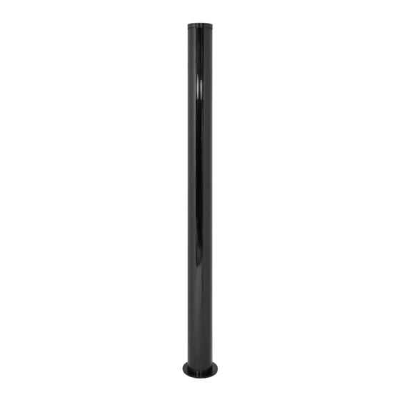
- Page 1 GARDEN-TOWER MAGNUS DUAL IR+MW TECHNOLOGY COLUMNS Available in terminal and bi-directional versions Installation and user manual MADE IN ITALY...
- Page 2 • Installation ……………………………………………………………………………………………………………………………. 23 • Manual configuration by dip-switch ……………………………………………………………………………………... 23 • Control through software (RS485) …………………………………………………………………………………………. 25 Warnings and OR – AND function Page 30 Technical features and consumption Page 31 GARDEN-TOWER MAGNUS Installation and user manual Page 2 of 32...
-
Page 3: Introduction And Warnings
(24Vac). • The installation should be performed by qualified personnel. MITECH is not responsible for damages and / or barrier malfunctions caused by incorrect installation and / or improper use. GARDEN-TOWER MAGNUS... -
Page 4: Main Components
1 couple Tamper boards (1 RX + 1 TX) 3 couples Optical groups (3 RX + 3 TX) 1 couple Microwave (1 RX + 1 TX) Heating resistors 3 couples GARDEN-TOWER MAGNUS Installation and user manual Page 4 of 32... - Page 5 Available colours: white (WH) and cognac (CO) Embedded light fixture (white colour) with LUMYA lamp holder Height: 25 cm - E27 GAR PRCAP Anti-climbing pressure cap TW CAMCAP Universal camera support GARDEN-TOWER MAGNUS Installation and user manual Page 5 of 32...
-
Page 6: General Installation Instructions
Drill 4 holes of Ø 8 mm in the wall, level with the bracket fixing holes. Insert M8 steel gussets (not supplied) and fix the bracket. FRONT VIEW SIDE VIEW 20 cm 20 cm TOP VIEW Hole for cables passage Ø 32 GARDEN-TOWER MAGNUS Installation and user manual Page 6 of 32... - Page 7 FIXING WITH GUSSETS Drill 3 holes of Ø 8 mm in the ground, level with the base fixing holes. Insert M8 steel gussets (not supplied) and fix the base. GARDEN-TOWER MAGNUS Installation and user manual Page 7 of 32...
- Page 8 Insert the connecting bracket between the lower cap and the aluminum bar. BRACKET Screw 2 M6x20 screws through the bracket and the base and 2 M6x25 screws through the bracket and the bar. M6X25 M6X20 GARDEN-TOWER MAGNUS Installation and user manual Page 8 of 32...
- Page 9 Closing the column Position the top cover and screw it to the column using the supplied screws provided with o-ring. GARDEN-TOWER MAGNUS Installation and user manual Page 9 of 32...
- Page 10 WARNING: ENSURE THAT THE COLUMNS ARE INSTALLED IN A STRAIGHT ROW For a correct positioning of the columns, refer to the following diagram (contact the supplier for more information) RX/TX RX/TX RX/TX RX/TX RX/RX TX/TX GARDEN-TOWER MAGNUS Installation and user manual Page 10 of 32...
- Page 11 COLUMNS IR BEAMS AND ELECTROMAGNETIC WAVES TRANSMISSION WARNING Ensure no interference is caused by the presence of photocells for automatic gates or infrared cameras, as these may blind the barriers. GARDEN-TOWER MAGNUS Installation and user manual Page 11 of 32...
- Page 12 THERMAL SENSOR N.C. ALARM RELAY N.A. CONTROL TAMPER OUTPUT HEATING POWER AND INPUT (0 Volt) SUPPLY 24 Vac 24 Vac MASK MASKING OUTPUT (OC) S.LOW FBRX LOW SIGNAL OUTPUT (OC) DISQUALIFICATION GARDEN-TOWER MAGNUS Installation and user manual Page 12 of 32...
- Page 13 Barrier with 5 lenses: only jumper 5 inserted MI-TECH ALIGNMENT JUMPER 9/10 BEAM THERMAL SENSOR +12 V 12 Vdc POWER SUPPLY HEATING POWER 0 V GND SUPPLY 24 Vac 24 Vac TAMPER OUTPUT FBTX GARDEN-TOWER MAGNUS Installation and user manual Page 13 of 32...
-
Page 14: Power Supply
With a power supply it is possible to feed a pair of barriers (RX-TX or RX-RX or TX-TX). MOTHERBOARDS WARNINGS Always use filtered and stabilized 230 Vac voltage. Then check the cabling before connecting the power supply GARDEN-TOWER MAGNUS Installation and user manual Page 14 of 32... - Page 15 • the blinding led must be switched off • the AND and S.LOW jumpers must be set to OFF • the MASK and SPEED trimmer regulation must remain in vertical position GARDEN-TOWER MAGNUS Installation and user manual Page 15 of 32...
- Page 16 Move the TEST jumper on the TX motherboard to ON Alignment setting Move the TEST jumper on the first TX expansion board to ON Flat cable Jumper insertion Led TX GARDEN-TOWER MAGNUS Installation and user manual Page 16 of 32...
- Page 17 AND programming MI-TECH jumper to ON, on the RX motherboard. IMPORTANT: during the alignment phase, SPEED remember that the AND jumper must always S.LOW 9/10 BEAM be set to OFF. GARDEN-TOWER MAGNUS Installation and user manual Page 17 of 32...
-
Page 18: Settings And Programming
17°C in all environmental conditions. If the led is ON, the heating system is working correctly. POWER: Power supply The POWER led is the only one that is permanently ON in ordinary operating conditions. GARDEN-TOWER MAGNUS Installation and user manual Page 18 of 32... - Page 19 Not used. Connector T.P. Connect the special red/black cable supplied to the connector T.P. during alignment, see page 16. TX expansion board Jumper TEST To use during alignment, see page 16. GARDEN-TOWER MAGNUS Installation and user manual Page 19 of 32...
- Page 20 Maximum lobe height and aperture 100 m range: 1,2 m at 50 m Installation height From 80 to 90 cm from the ground Non-detection zones 1,0 m 2,0 m 3,0 m GARDEN-TOWER MAGNUS Installation and user manual Page 20 of 32...
- Page 21 LED: led activation Terminal board description: TAMPER IN: tamper input TAMPER OUT: tamper output 0 A B: RS485 ALARM: alarm output WARN: not used GND: 0 V VIN: +12 Vdc GARDEN-TOWER MAGNUS Installation and user manual Page 21 of 32...
- Page 22 LED: led activation Terminal board description: TAMPER IN: tamper input TAMPER OUT: tamper output 0 A B: RS485 ALARM: fault output WARN: not used GND: 0 V VIN: +12 Vdc GARDEN-TOWER MAGNUS Installation and user manual Page 22 of 32...
-
Page 23: Installation
Installation Introduction The MITECH antennas can be managed manually via the dip-switches on both the RX and TX modules or by using the MITECH Radar Barrier configuration proprietary program. IMPORTANT: the modules always keep the last saved configuration in memory even in the event of a power failure. - Page 24 IMPORTANT It is only possible to enter the configuration mode once to program the dip-switches. In manual control mode it is not possible to make changes using the software. GARDEN-TOWER MAGNUS Installation and user manual Page 24 of 32...
- Page 25 MIRS485 module - MITECH radar barrier configuration program start The MITECH Radar Barrier Configuration program allows, via the RS485 serial connection, the maximum and simultaneous management of 16 pairs of antennas, using only one COM port. In case it is necessary to manage more than 16 pairs of antennas, more COM ports must be used.
- Page 26 With the value 0 db the signal is attenuated by 4 dB. To save the modification, click with the mouse on the red cell of the address you are configuring (figure 4). Figure 1 Figure 2 Figure 3 Figure 4 GARDEN-TOWER MAGNUS Installation and user manual Page 26 of 32...
- Page 27 OK (figure 3). To save the modification, click with the mouse on the red cell of the address you are configuring (figure 4). Figure 3 Figure 1 Figure 2 Figure 4 GARDEN-TOWER MAGNUS Installation and user manual Page 27 of 32...
- Page 28 IMPORTANT: once the display panel is activated, the configuration table is automatically inhibited and parameters can no longer be changed. To reactivate the commands, click on the Pause button. Pause GARDEN-TOWER MAGNUS Installation and user manual Page 28 of 32...
- Page 29 TERM jumper in the last connected module. IMPORTANT For all connections it is necessary to respect the following connection diagram: A with A - B with B GARDEN-TOWER MAGNUS Installation and user manual Page 29 of 32...
- Page 30 6. Supply the device with a stabilized voltage of 13.8 Vdc. 7. Installation must be carried out by qualified personnel. 8. MITECH is not responsible for damages and / or malfunctions of the barriers caused by incorrect installation and / or improper use.
- Page 31 TW MA 253 GAR MA 253-BD 450 mA TW MA 253-BD GAR MA 303 200 mA 250 mA 450 mA TW MA 303 GAR MA 303-BD 450 mA TW MA 303-BD GARDEN-TOWER MAGNUS Installation and user manual Page 31 of 32...
- Page 32 Via Ramazzone, 23 Fax: +39 02.48025620 20146 Milano – Italy 43010 Fontevivo (PR) – Italy tech@mitech-security.com www.mitech-security.com MADE IN ITALY GARDEN-TOWER IR - Rev. 20 - 03/2019 - MITECH srl reserves the right to change the information in this document without warning.
Need help?
Do you have a question about the GARDEN-TOWER MAGNUS and is the answer not in the manual?
Questions and answers