
Related Manuals for MITECH FOSTER POWER


Summary of Contents for MITECH FOSTER POWER
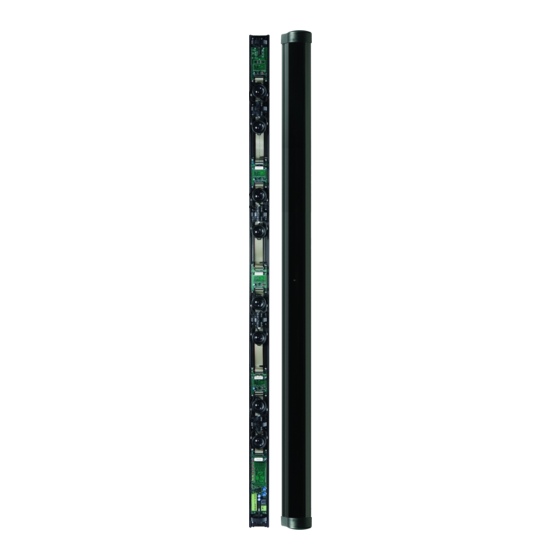
- Page 1 FOSTER POWER ACTIVE INFRARED BARRIER WITH INTEGRATED POWER SUPPLY Installation and user manual MADE IN ITALY...
- Page 2 Alignment Page 11 Settings and programming Page 13 • Description of signalling leds ……………………………………………………………………………………………….. 14 • Description of jumper settings ………………………………………………………………………………………………15 Technical features and consumption Page 16 Notes Page 17 FOSTER POWER Installation and user manual Page 2 of 20...
- Page 3 Introduction and warnings INTRODUCTION FOSTER POWER is a perimeter IR barrier with crossed beams for protection of external areas, with a pleasant design and compact dimensions. Pre-cabled and ready for installation FOSTER POWER is composed of a transmitting and a receiving unit.
- Page 4 2 to 5 Flat cable Motherboard from 2 to 5 Expansion board Tamper board Accessories Part No. Code Description Pole-mounting bracket FTN SUP (1kit comprises two pieces A+B) Wall-mounting bracket FTN WL FOSTER POWER Installation and user manual Page 4 of 20...
- Page 5 Do not use switching power supplies that might cause electrical disturbances . Bracket mounting options Pole mounting (ø 48 mm) – FTN SUP Pole mounting Rear bracket insertion Wall mounting – FTN WL Rear bracket insertion FOSTER POWER Installation and user manual Page 5 of 20...
- Page 6 Installation solutions POLE FIXING POLE FIXING AREA AREA TO PROTECT TO PROTECT WALL FIXING COMBINED WITH TOWER/GARDEN IR COLUMNS AREA AREA TO PROTECT TO PROTECT Overlapped solution: Single-lens barriers Double-lens barriers FOSTER POWER Installation and user manual Page 6 of 20...
- Page 7 Example of how to protect an independent building The FOSTER POWER barriers come with crossed beams for maximum protection. For visibility purposes, the beams in this drawing are linear. BARRIERS IR BEAMS RX-TX TRANSMITTION RX-TX RX-TX RX-TX BARRIERS WARNING Ensure no interference is caused by the presence of photocells for automatic gates or infrared cameras, as these may blind the barriers.
- Page 8 THERMAL SENSOR N.C. ALARM RELAY N.A. CONTROL TAMPER OUTPUT HEATING POWER AND INPUT (0 Volt) SUPPLY 24 Vac 24 Vac MASK MASKING OUTPUT (OC) S.LOW FBRX LOW SIGNAL OUTPUT (OC) DISQUALIFICATION FOSTER POWER Installation and user manual Page 8 of 20...
- Page 9 Barrier with 5 lenses: only jumper 5 inserted MI-TECH ALIGNMENT JUMPER 9/10 BEAM THERMAL SENSOR +12 V 12 Vdc POWER SUPPLY HEATING POWER 0 V GND SUPPLY 24 Vac 24 Vac TAMPER OUTPUT FBTX FOSTER POWER Installation and user manual Page 9 of 20...
- Page 10 WEIGHT AND DIMENSIONS weight: 0,500 Kg - dimensions: H45 x L130 x P45 mm WARNINGS Always use filtered and stabilized 230 Vac voltage. Then check the cabling before connecting the power supply FOSTER POWER Installation and user manual Page 10 of 20...
- Page 11 • the blinding led must be switched off • the AND and S.LOW jumpers must be set to OFF • the MASK and SPEED trimmer regulation must remain in vertical position FOSTER POWER Installation and user manual Page 11 of 20...
- Page 12 Move the TEST jumper on the TX motherboard to ON Alignment setting Move the TEST jumper on the first TX expansion board to ON Flat cable Jumper insertion Led TX FOSTER POWER Installation and user manual Page 12 of 20...
- Page 13 AND programming MI-TECH jumper to ON, on the RX motherboard. IMPORTANT: during the alignment phase, SPEED remember that the AND jumper must always S.LOW 9/10 BEAM be set to OFF. FOSTER POWER Installation and user manual Page 13 of 20...
- Page 14 17°C in all environmental conditions. If the led is ON, the heating system is working correctly. POWER: Power supply The POWER led is the only one that is permanently ON in ordinary operating conditions. FOSTER POWER Installation and user manual Page 14 of 20...
- Page 15 Not used. Connector T.P. Connect the special red/black cable supplied to the connector T.P. during alignment, see page 16. TX expansion board Jumper TEST To use during alignment, see page 16. FOSTER POWER Installation and user manual Page 15 of 20...
- Page 16 BARRIER TOTAL CONSUMPTION FTN 102 D 120 mA 110 mA 230 mA FTN 153 D 120 mA 150 mA 270 mA FTN 204 D 120 mA 230 mA 350 mA FOSTER POWER Installation and user manual Page 16 of 20...
- Page 17 Notes: FOSTER POWER Installation and user manual Page 17 of 20...
- Page 18 FOSTER POWER Installation and user manual Page 18 of 20...
- Page 19 FOSTER POWER Installation and user manual Page 19 of 20...
- Page 20 Via Ramazzone, 23 Fax: +39 02.48025620 20146 Milano – Italy 43010 Fontevivo (PR) – Italy tech@mitech-security.com www.mitech-security.com FOSTER POWER Rev.3 – 03/2019 – MITECH srl reserves the right to change the information in this document without warning. MADE IN ITALY...
Need help?
Do you have a question about the FOSTER POWER and is the answer not in the manual?
Questions and answers