Table of Contents
Advertisement
Quick Links
Advertisement
Table of Contents

Subscribe to Our Youtube Channel
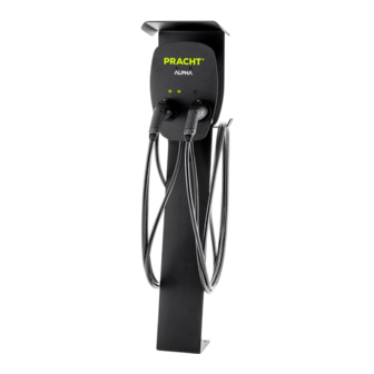
Summary of Contents for PRACHT ALPHA
- Page 1 ALPHA (NRG1000) MANUAL Status: December 2020...
-
Page 2: Table Of Contents
TABLE OF CONTENTS NOTES ON THIS DOCUMENT ................................ 2 SAFETY, INSTALLATION, AND USE ..............................2 FURTHER INSTRUCTIONS FOR USE ..............................3 SCOPE OF DELIVERY ..................................4 TECHNICAL DATA ................................... 5 ASSEMBLY ....................................6 PREREQUISITES ..................................6 WALL MOUNTING ..................................6 ELECTRICAL CONNECTION ................................ -
Page 3: Notes On This Document
NOTES ON THIS DOCUMENT Before installing and using the wallbox the instructions must be read and understood in full by the installer and each user. Please keep the instructions for the entire service life of the wallbox in order to be able to access them later. Also observe the operating instructions for your electric vehicle. -
Page 4: Further Instructions For Use
FURTHER INSTRUCTIONS FOR USE Vessels containing liquids must not be placed on the charging station. • Avoid bending or running over the charging cable. • When the charging station is not in use, the charging cable must be coiled up on the device provided for this purpose •... -
Page 5: Scope Of Delivery
SCOPE OF DELIVERY Wallbox ALPHA, pre-assembled • • Jumper, pre-assembled • Operating instructions • Drilling template • Fixing material, consisting of: • 1x mounting bracket left 1x mounting bracket, right 8x self-tapping screws for mounting brackets Check the scope of delivery for completeness. -
Page 6: Technical Data
TECHNICAL DATA ALPHA – NRG1000 3.7 (1-phase) / 11 (3-phase) Charging power mode 3 [kW] per output 7.4 (1-phase) / 22 (3-phase) Rated voltage UN [V] 230 (1-phase) / 400 (3-phase) Rated frequency Residual current protection AC / DC [mA] 30 / 6 Max. -
Page 7: Assembly
ASSEMBLY PREREQUISITES The wallbox may only be installed by a trained electrician. Before installation the device must be thoroughly checked for damage. The wallbox is only suitable for vertical installation. The wallbox may be installed indoor or in protected outdoor areas, such as under canopies. The ambient temperature at the installation site must be in the range of -20°C to +40°C. -
Page 8: Electrical Connection
ELECTRICAL CONNECTION The supply line of the wallbox must be disconnected from the power supply during installation work. CONNECTION TO THE MAINS The supply line must be correctly fused. 1. Pull the supply cable into the box. 2. Connect the supply cable as shown in figure 2 and then relieve the strain and seal it using the cable gland. CONNECTING RCD SWITCH TERMINALS... -
Page 9: Initial Commissioning
The setting is made by attaching the jumper to the corresponding position on the control unit. The slots on this can be found with the label "I max". The assignment of the slots is shown in the following table: 1-PHASE CHARGING 2-PHASE CHARGING 3-PHASE CHARGING 2 Vehicle... -
Page 10: Operation
OPERATION This charging station is suitable for electrically charging one or two vehicles with type 2 charging couplings. Please also refer to the operating instructions for your electric vehicle. LED-DISPLAY The wallbox is equipped with a separate LED indicator light for each charging cable, which shows the current status during operation. -
Page 11: Sequential Charging
SEQUENTIAL CHARGING Note: The time-delayed allocation of the charging current is not supported by all electric vehicles. A charging current of at least 6A is required for each vehicle to be charged. If the wallbox has been configured for a low charging current, this may mean that not both vehicles can be charged at the same time. -
Page 12: Troubleshooting
The charging process was interrupted. • Start the charging process again. To do so, disconnect the wallbox from the vehicle for 10 seconds. CONTACT ADDRESS PRACHT Industry GmbH Am Seerain 3, 35232 Dautphetal-Buchenau, Germany Phone +49 6466 9140-900 info@prachtenergy.com, www.prachtenergy.com...


Need help?
Do you have a question about the ALPHA and is the answer not in the manual?
Questions and answers