
Related Manuals for Federal Signal Corporation Valor FSJoin


Summary of Contents for Federal Signal Corporation Valor FSJoin
- Page 1 Valor FSJoin Light Bar Manual ® Installation, Maintenance, and Service Manual 25500671 REV. A0 1020 Printed in U.S.A. © Copyright 2020 Federal Signal Corporation...
- Page 2 A copy of this limited warranty can also be obtained by written request to Federal Signal Corporation, 2645 Federal Signal Drive, University Park, IL 60484, email to info@fedsig.com or call +1 708-534-3400.
-
Page 3: Table Of Contents
Contents Safety Messages..........................5 Safety Message to Installers and Service Personnel of Warning Lights ...........5 Safety Message to Operators of Warning Light Equipment ..............8 An Overview of the Valor Light Bar ..................... 10 LED Lights, Colors, and Flash Patterns ....................10 Modular Connector System ........................ - Page 4 Tables Table 1 Dimensions ............................11 Table 2 Light Specifications ..........................11 Table 3 Electrical and Temperature ....................... 11 Table 4 Control wires from the Serial Interface Module with Default Programming ....... 14 Table 5 SignalMaster control wires and warning patterns ..............22 Table 6 Troubleshooting tips ........................
-
Page 5: Safety Messages
Safety Messages Safety Messages For your safety, read and understand this manual thoroughly before installing, operating, and servicing the Valor light bar. The safety messages presented in this ® chapter and throughout the manual are reminders to exercise extreme care at all times. - Page 6 Safety Messages • A light system is a high current system. In order for the system to function properly, a separate negative (–) connection and positive (+) connection must be made. All negative connections should be connected to the negative battery terminal and a suitable fuse should be installed on the positive battery terminal connection as close to the battery as possible.
- Page 7 Safety Messages • DO NOT install equipment or route wiring (or the plug in cord) in the deployment path of an airbag. • If a vehicle seat is temporarily removed, verify with the vehicle manufacturer if the seat needs to be recalibrated for proper airbag deployment. •...
-
Page 8: Safety Message To Operators Of Warning Light Equipment
Safety Messages • Scratched or dull reflectors, mirrors, or lenses will reduce the effectiveness of the lighting system. Avoid heavy pressure and use of caustic or petroleum based products when cleaning the lighting system. Replace any optical components that may have been scratched or crazed during system installation. •... - Page 9 Safety Messages • It is important that you fully understand how to safely operate this warning system before use. • Only operate your vehicle and its light/sound system per your department’s Standard Operating Procedures. • If a selected function does not perform properly or if any of the lamps remain illuminated when the control is off, disconnect the power connector from the control unit and contact the nearest service center.
-
Page 10: An Overview Of The Valor Light Bar
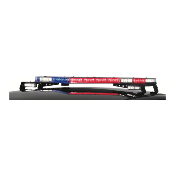
An Overview of the Valor Light Bar ® An Overview of the Valor Light Bar The Valor Light Bar is a single-level LED light bar with ROC™ (Reliable On-Board Circuitry) and Solaris ® LED technologies. ROC eliminates approximately 85 percent ™... -
Page 11: Fsjoin
Light Bar ® FSJoin Valor FSJoin light bars allow flash patterns to synchronize with other FSJoin compatible devices. Light bar patterns and features can be programmed on an individual light head with the Convergence Network Configuration Software. Outputs or light heads set to the same flash rate automatically synchronize. A variety of system features can be programmed with the Convergence Network Configuration Software (available on the Federal Signal website at www.fedsig.com). -
Page 12: Preparing The Valor For Installation
Preparing the Valor for Installation Preparing the Valor for Installation Taking the preparatory steps in this chapter before mounting and wiring the light bar to a vehicle will help ensure that your installation is fast, easy, and error free. In addition to instructions for quick testing the light bar, this section has instructions for changing default settings and flash patterns with the Serial Interface Module. -
Page 13: Figure 1 Serial Interface Module Connections For Programming
Preparing the Valor for Installation The numbers in the steps below refer to the wires in Figure 1. To connect the Valor to the battery and Serial Interface Module: 1. To supply power to the light bar, use a fully-charged 12-volt automotive battery with terminal lugs. -
Page 14: Identifying The Control Wires For Flash Patterns
Preparing the Valor for Installation Identifying the Control Wires for Flash Patterns This section describes how to program flash patterns by applying 12 Vdc to the control wires in the 24-pin harness of Serial Interface Module. Table 4 shows the control wires and colors. -
Page 15: Wiring The Valor In The Vehicle
Wiring the Valor in the Vehicle Wiring the Valor in the Vehicle Before proceeding, ensure that the light bar has been installed on the vehicle roof in accordance with the instructions included with the mounting kit. Depending on the type of vehicle and mounting system feature, there are two options available for installing the light bar to the roof of the vehicle: hook-on mounting or permanent mounting. - Page 16 Wiring the Valor in the Vehicle 3. Determine where to mount the controlling equipment: • Trunk or remote location • Console AIRBAG DEPLOYMENT: Do not install equipment or route wiring in the deployment path of an airbag. Failure to observe this warning will reduce the effectiveness of the airbag or potentially dislodge the equipment, causing serious injury or death.
-
Page 17: Connecting Power To The Light Bar
Wiring the Valor in the Vehicle Connecting Power to the Light Bar NOTE: Plan the location of the wire-routing hole in the vehicle roof so that the power and communication cables do not have tight bends and have some slack to allow disconnection on removal. - Page 18 Wiring the Valor in the Vehicle To mount the Serial Interface Module and make the power connections: 1. Use the Serial Interface Module as a template and scribe four drill-position marks at the selected mounting location. Mounting centers are 2.00 in x 5.95 in (5.08 cm x 15.11 cm).
-
Page 19: Wiring The Serial Interface Module
Wiring the Valor in the Vehicle Figure 2 Relay-isolating devices with large filter capacitors RELAY STROBE SUPPLY CONTROL LEAD (12 Vdc SIGNAL ACTIVATED) +12 Vdc FUSE* 290A6562 *FUSE AMPERAGE DEPENDS ON AMPERAGE OF DEVICES Wiring the Serial Interface Module FUSE ELECTRICAL SOURCES: Always fuse current/voltage sources with a fuse connected near the power source. - Page 20 Wiring the Valor in the Vehicle Priority Modes 1, 2, and 3 To activate a priority mode, apply 12 Vdc (+BAT) to a mode control wire. Mode 3 (black/red) overrides Mode 2 (blue/white), and Mode 2 overrides Mode 1 (blue). You can program one of the flash patterns in the light bar to each Mode input.
- Page 21 Wiring the Valor in the Vehicle Takedown Lights When 12 Vdc (+BAT) is applied to the Takedown control wire (white/black), the takedown LEDs turn on. Takedown overrides Flash Takedown/Alley and Front Cutoff. Scene Light, Left and Scene Light, Right This function applies only to light bars with Spectralux Technology (Valor and Vision SLR).
-
Page 22: Table 5 Signalmaster Control Wires And Warning Patterns
Wiring the Valor in the Vehicle Internal SignalMaster (Factory Default) NOTE: If the SignalMaster is not activated by a control head or an external controller, the SignalMaster LED heads flash with the selected priority mode (Mode 1, 2, or 3) of operation. -
Page 23: Figure 4 Signalmaster Flash Sequences
Wiring the Valor in the Vehicle Figure 4 SignalMaster flash sequences LEFT CENTER RIGHT WARN 1 WARN 2 WARN 3 WARN 4 290A6578D Installation, Maintenance, and Service Manual Federal Signal www.fedsig.com... -
Page 24: Figure 5 Signalmaster Functions Wired To 12 Vdc For Internal Serial Interface Module Control
Wiring the Valor in the Vehicle Figure 5 SignalMaster control functions wired to 12 Vdc for internal Serial Interface Module control J1 CABLE TO POWER (+12 Vdc) SERIAL INTERFACE MODULE BLACK/RED MODE 3 BLUE/WHITE MODE 2 BLUE MODE 1 RED/WHITE STEADY BURN (or SCENE LIGHT, LEFT with SW-2 Switch 3 down [ON] in the Serial Interface Module) -
Page 25: Figure 6 Signalmaster Functions Wired To Ground For External Serial Interface Module Control
Wiring the Valor in the Vehicle Figure 6 SignalMaster control functions wired to ground for external Serial Interface Module control J1 CABLE TO POWER (+12 Vdc) SERIAL INTERFACE MODULE BLACK/RED MODE 3 MODE 2 BLUE/WHITE BLUE MODE 1 STEADY BURN RED/WHITE (or SCENE LIGHT, LEFT with SW-2 Switch 3 down [ON] in the Serial Interface Module) -
Page 26: Figure 7 Typical Connections With A Signalmaster Controller (External Control)
Wiring the Valor in the Vehicle WHT/RED RED/GRN BLU/RED ORG/GRN GRN/BLK/WHT BLU (MODE 1) BLU/WHT (MODE 2) BLK/RED (MODE 3) WHT/BLK (TD) GRN/BLK (L. AL) ORG/RED (R. AL) Valor Light Bar ® Federal Signal www.fedsig.com... -
Page 27: Figure 8 Typical Connections With A Sw400Ss Switch Module (Internal Control)
Wiring the Valor in the Vehicle +12 V RED (LEFT) GRN (CENTER) GRN/BLK/WHT (RIGHT) ORG/GRN (WARN1) ORG (WARN2) WHT/RED (FAST) BLU (MODE 1) BLU/WHT (MODE 2) BLK/RED (MODE 3) WHT/BLK (TD) GRN/BLK (L. AL) ORG/RED (R. AL) Installation, Maintenance, and Service Manual Federal Signal www.fedsig.com... -
Page 28: Figure 9 Typical Connections With A Smartsiren Model Ss2000Sm Controller
Wiring the Valor in the Vehicle WHT (1) BRN (2) GRN/BLK/WHT GRN (3) ORG/GN) ORN (4) PRP (5) BLU/RED GRA (6) RED/GRN YEL (7) WHT/RED BLU (8) NONE (9) RED+ (10) BLK− (11) Valor Light Bar ® Federal Signal www.fedsig.com... -
Page 29: Figure 10 Typical Connections With A Non-Signalmaster Controller
Wiring the Valor in the Vehicle BLU (MODE 1) BLU/WHT (MODE 2) BLK/RED (MODE 3) WHT/BLK (TD) GRN/BLK (L. AL) ORG/RED (R. AL) Installation, Maintenance, and Service Manual Federal Signal www.fedsig.com... -
Page 30: Figure 11 Typical Connections With A Pa640 Controller
Wiring the Valor in the Vehicle BLK/RED (MODE 3) RED/BLK (FL TKD/AL) BLU/WHT (MODE 2) BLU (MODE 1) WHT/BLK (TD) GRN/BLK (L.AL) ORG/RED (R.AL) Valor Light Bar ® Federal Signal www.fedsig.com... -
Page 31: Maintaining And Servicing The Valor
Maintaining and Servicing the Valor Maintaining and Servicing the Valor This chapter describe how to maintain and service the Valor light bar. Establishing a regular maintenance and inspection schedule extends the life of the light bar and ensures safety. For service, support, or replacement parts, contact the Federal Signal Service Department at 1-800-433-9132, 7 a.m. -
Page 32: Removing And Reinstalling The Light Bar Lens
Maintaining and Servicing the Valor Removing and Reinstalling the Light Bar Lens The light bar lens, which is the top half of the Valor housing, covers the ROC (Reliable Onboard Circuitry) PCBs and controller PCB. Tool required: T27 Torx driver Removing the Lens To remove the lens: 1. -
Page 33: Replacing A Pcb
Maintaining and Servicing the Valor Reinstalling the Lens To reinstall the lens: 1. Reinstall the gasket and lens. To prevent cross-threading the barrel nuts, back them counterclockwise until you hear the click of the threads engaging. 2. Tighten the barrel nuts to 16-24 in-lb in the sequence shown in Figure 12 on page Replacing a PCB The Valor light bar has two front, two rear, and two end ROC PCBs as well as a controller PCB (Figure 15). -
Page 34: Disconnecting/Connecting Power And Cat5 At The Light Bar
Maintaining and Servicing the Valor 4. Inspect the O-rings and the lip seal for deformation, brittleness, cuts, or tears. To maintain watertightness, replace a questionable O-ring or seal. 5. Note and record the connection to the PCB (Figure 13 on page 33), then lift it and disconnect the harnesses. -
Page 35: Figure 15 Secondary Lock Mechanism In The Plug And Receptacle
Maintaining and Servicing the Valor Figure 15 Secondary lock mechanism in the plug and receptacle CPA (connector position assurance) Locking Latch Locking Ramp Receptacle Plug Disconnecting a Cable at the Light Bar To disconnect the power or CAT5 cable: 1. Pull back the CPA on the receptacle. 2. - Page 36 Maintaining and Servicing the Valor Reconnecting a Cable at the Light Bar To reconnect the power or CAT5 cable: 1. Firmly push the connectors together until you feel them snap together and you hear a click. This tactile and audible confirmation ensures that the connectors are properly and fully mated.
-
Page 37: Troubleshooting The Light Bar
Maintaining and Servicing the Valor Troubleshooting the Light Bar This section provides troubleshooting assistance for common problems. If you have any questions left unanswered, call the Federal Signal Service Department at 1-800- 433-9132, 7 a.m. to 5 p.m., Monday through Friday (CT). Table 6 Troubleshooting tips Problem Corrective Action... -
Page 38: Quick Testing The Valor With The Light Bar Test
Maintaining and Servicing the Valor Problem Corrective Action The light bar has a delayed • Ensure that the connections on the Serial Interface Module are kept response to being shut off separate from strobe supplies. • Check all the ground connections, especially on the Serial Interface Module. -
Page 39: Testing The Steady Burn Leds (Hotfoot Only)
(default setting). 2. Remove 12 Vdc from the Mode and Steady Burn control wires. Getting Technical Support and Service For technical support and service, please contact: Service Department Federal Signal Corporation Phone: 1-800-433-9132 Email: empserviceinfo@fedsig.com www.fedsig.com Getting Repair Service The Federal Signal factory provides technical assistance with any problems that cannot be handled locally. -
Page 40: Replacement Parts
Getting Technical Support and Service Replacement Parts This section contains a partial list of replacement parts. To order replacement parts, call the Federal Signal Service Department at 1-800-433-9132 or 1-708-534-3400, 7 a.m. to 5 p.m., Monday through Friday (Central Time) or contact your nearest distributor.
Need help?
Do you have a question about the Valor FSJoin and is the answer not in the manual?
Questions and answers