
Related Manuals for Südwind AMBIENTIKA ECO


Summary of Contents for Südwind AMBIENTIKA ECO
- Page 1 AMBIENTIKA ECO Handbuch für Installation und Wartung Manuale installazione e manutenzione Instructions and maintenance manual...
- Page 2 EINFÜHRUNG Dieses Handbuch enthält technische Beschreibungen von Gerät, Installation, Montage und Instandhaltung sowie technische Daten und richtet sich einzig und allein an das qualifizierte Personal, das mit der Installation und Instandhaltung des Produktes befasst ist. ZWECKBESTIMMUNG Das Produkt ist nach allen Vorschriften der aktuellen Gesetze hergestellt worden und wird installiert, um einen stetigen Luftaustausch im Inneren von Räumlichkeiten zu gewährleisten.
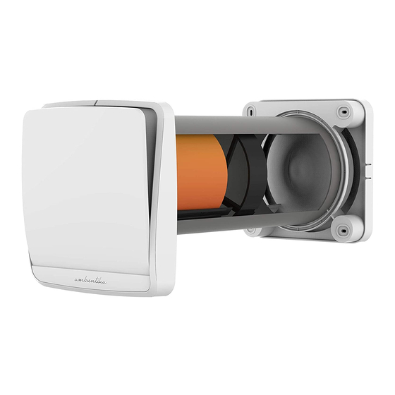
- Page 3 INHALT 1 – Frontale Klappe für das Abdeckgitter 4i – Befestigung für die Innenwand 2 – Abdeckgitter mit elektrischen Anschlüssen 4e – Befestigung für die Außenwand 3 – Haupteinheit 5 – Externe Wetterschutzabdeckung 6 – Einbaurohr (500 mm)
-
Page 4: Technische Daten
7 – Keramik-Wärmetauscher – Allgemeine Hinweise11 – 8 – Filter Garantieschein RAEE 9 – Handbuch für Installation und 12 – Verpackung Instandhaltung 13 – Hinweise für das Auspacken des Produktes TECHNISCHE DATEN Der Wohnraumlüfter ist in die Klasse II eingestuft worden. Die Schutzklasse ist IPX4. -
Page 5: Montage
AUFBAU Das Produkt besteht aus einer Haupteinheit mitsamt einer Wandbefestigung, die an der Innenwand des zu belüftenden Raums angebracht wird, aus einem Einbaurohr, in dem der Wärmetauscher aus Keramik und die Filter angebracht sind sowie einer externen Wetterschutzabdeckung mitsamt einer Wandbefestigung Wärmetauscher Externe Abdeckung aus Keramik... - Page 6 Das Bohrloch muss durch die gesamte Mauer reichen und nach außen ein Gefälle von 1 bis 2 Grad aufweisen. Um das mitgelieferte Einbaurohr verwenden zu können, darf die Mauer eine Stärke von 500 mm nicht überschreiten. Um das Produkt installieren zu können, darf die Wandstärke allerdings auch nicht unter 250 mm liegen.
- Page 7 M=500mm Hat man die Länge des Einbaurohres (6) an die Wandstärke angepasst, muss die Befestigung für die Außenwand (4e) an der Außenmauer angebracht werden, wie dies im folgenden Schaubild dargestellt ist. Positionieren Sie den Passring der Befestigung für Außenwand (4e) innerhalb Einbaurohres (6).
-
Page 8: Elektrische Anschlüsse
Lassen Sie die Abdeckung (5) wie im folgenden Schaubild gezeigt in die Befestigung für die Außenwand (4e) einrasten. 2. ELEKTRISCHE ANSCHLÜSSE Die Installation des Gerätes ist ausschließlich qualifiziertem Personal vorbehalten. Stellen Sie sicher, dass die Spannung an dem Punkt, wo das Gerät installiert wird, jener entspricht, die auf dem Datenblatt des Produktes ausgewiesen ist. - Page 9 (6) eingepasst werden, wie es obige Abbildung zeigt. Mit Hilfe einer Wasserwaage können dann die vier Bohrlöcher für die Befestigung an der Innenwand (4i) eingezeichnet werden. Anders als bei der Befestigung an der Außenmauer muss innen das Netzkabel bis zu den bereits mitgelieferten ab-isolierten Kabeln gezogen werden.
- Page 10 Verbinden eines Stromkabels, aus der Wand kommend: Nach dem Einsetzen der Dübel, bevor Sie mit der Montage fortfahren, entfernen Sie den Klemmenblock aus der Halterung (4) und führen Sie die Kabel durch die entsprechende Führung. VERBINDUNG EINES KABELS VON AUSSEN AN DAS GEHÄUSE: Brechen Sie die Einkerbung wie unten ersichtlich aus Entfernen Sie den Klemmenblock aus der Halterung (4) und führen Sie die Kabel durch die entsprechende Führung.
- Page 12 DIREKTER ANSCHLUSS Bevor Sie fortfahren, stellen Sie sicher, dass die Netzkabel (Leiter und Neutralleiter) bis zur dafür vorgesehenen Aussparung gezogen worden sind. Nehmen Sie die Befestigung für die Innenwand (4i) sowie alle notwendigen Werkzeuge zur Hand, um die Netzkabel an die mitgelieferten abisolierten Kabel in der vorgesehenen Aussparung anzuschließen.
-
Page 13: Wartung
Um die Geschwindigkeit über einen Wandschalter regulieren zu können, müssen die beiden Schalterausgänge – wie im Schaubild gezeigt – mit „S1“ und „S2“ verbunden werden. WARTUNG Alle Wartungsarbeiten am Gerät sind ausschließlich qualifiziertem Fachpersonal vorbehalten. Versichern Sie sich, dass während der Wartungsarbeiten am Gerät im Netz im betroffenen Raum kein Strom fließt. - Page 14 Einmal installiert, muss das Produkt so aufgebaut sein, wie dies im obigen Schaubild veranschaulicht wird. 1. WARTUNGSZEITRÄUME Wir empfehlen, die Filter (8) und den Wärmetauscher aus Keramik (7) alle drei Monate zu säubern. Alle zwei Jahre sollten die Filter ausgetauscht werden. Um die richtigen Filter zu bekommen, wenden Sie sich bitte an das SÜDWIND-Team oder an den Monteur.
- Page 15 Ziehen Sie den Wärmetauscher aus Keramik zusammen mit den Filtern (8+7+8) an der dafür vorgesehenen Schnur aus dem Einbaurohr (siehe Abbildung). Nehmen Sie die Filter (8) aus ihrer Halterung und säubern Sie diese zuerst mit Hilfe eines Staubsaugers oder mit fließendem Wasser vom Staub. Bevor sie wieder eingesetzt werden, müssen die Filter komplett getrocknet sein.
- Page 16 Während die Filter gesäubert/gewechselt werden, sollte auch eventueller Schmutz vom Wärmetauscher aus Keramik entfernt werden. WASCHEN SIE DEN WÄRMETAUSCHER AUS KERAMIK NICHT MIT WASSER! Sind die Filter (8) sauber und trocken, müssen sie wieder in ihre entsprechenden Halterungen auf dem Wärmetauscher (7) eingesetzt werden.
- Page 17 3. REINIGUNG ABDECKGITTER UND VENTILATOR Nachdem Filter und Wärmetauscher gesäubert worden sind, müssen sie wieder am vorgesehenen Platz in der Mitte des Einbaurohres positioniert werden. Danach nimmt man die Haupteinheit (1+2+3) zur Hand und die frontale Klappe (1) ab, indem zuerst die oberen, dann die unteren Haken gelöst werden. Mit Hilfe eines Schlitzschraubenziehers löst man auch die Haltezähne des Abdeckgitters (2) und kann dieses von der Haupteinheit (3) lösen.
- Page 18 WIEDERHERSTELLUNG DES GERÄTES NACH DER REINIGUNG Setzen Sie die Haupteinheit (3) gemeinsam mit dem Abdeckgitter (2) und der frontalen Klappe (1) wieder auf die Befestigung für die Innenwand (4i). ACHTUNG: Sollten mehrere Geräte gleichzeitig gereinigt werden, achten Sie darauf, dass jede Haupteinheit wieder in das Gerät eingesetzt wird, aus dem sie entfernt worden ist.
- Page 19 ANLEITUNGEN FÜR EINE KORREKTE FUNKTIONSWEISE Geschwindigkeits-Auswahl (1/2) Hauptschalter (0/1) 1. Einschalten Nachdem das Gerät von qualifiziertem Fachpersonal montiert worden ist, muss es mit Hilfe des Hauptschalters „0/1“ an der Seite der Haupteinheit eingeschaltet werden. Stellen Sie sicher, dass die Leuchtanzeige sich eingeschaltet hat. Wird das Abdeckgitter geöffnet, beginnt das Gerät, normal zu funktionieren und im 70- SekundenRhythmus zwischen Ab- und Ansaugen der Luft zu wechseln.
-
Page 20: Problembehandlung
Sollte das Gerät von einem Wandschalter aus gesteuert werden, muss dieser in die Position „0“ gestellt werden. Am Gerät bleibt der Hauptschalter in der Position „1“. PROBLEMBEHANDLUNG Sollte sich das Gerät nicht einschalten oder die Funktionsweise bzw. der Lärm nicht als normal erachtet werden, muss das Gerät noch einmal ausgeschaltet werden, indem der Hauptschalter „0/1“... - Page 21 ITALIANO INTRODUZIONE Questo manuale tecnico contiene descrizioni tecniche, operazioni di installazione, montaggio, manutenzione e dati tecnici esclusivamente rivolti al personale qualificato addetto alla installazione e manutenzione del prodotto. DESTINAZIONE D’USO Il prodotto è costruito a regola d’arte e viene installato per dare la possibilità di un ricambio costante di aria all’interno della stanza.
-
Page 23: Parametri Tecnici
CONTENUTO 1- Frontale estetico copertura serranda 7- Scambiatore ceramico 2- Serranda 8- Filtri 3- Unità principale 9- Manuale installazione e manutenzione 4i- Fissaggio a parete interno con connessioni 10- Avvertenze generali elettriche 11- Foglio di garanzia RAEE 4e- Fissaggio a parete esterno 12- Imballo prodotto 5- Convogliatore esterno 13- Avvertenza estrazione prodotto... - Page 24 Il recuperatore è stato progettato per installazioni in luoghi chiusi. Le temperature di esercizio sono comprese tra -20°C e 50°C con umidità relativa massima 80%. Il design del recuperatore è in continua evoluzione, pertanto, alcuni modelli potrebbero differire da quanto descritto nel presente manuale. MISURE, MM -ECO Velocità...
-
Page 25: Installazione
Scambiatore Convogliatore ceramico esterno con attacco a parete Tubo da incasso Filtro esterno Filtro interno Unità principale con attacco a parete INSTALLAZIONE L’installazione dell’apparecchio è destinata solo ed esclusivamente a personale qualificato. Assicurarsi che il collegamento di rete nel locale di installazione venga disconnesso prima delle operazioni elettriche di montaggio. - Page 26 1) MONTAGGIO Dopo aver individuato l’area nella quale si intende installare il prodotto segnare il centro del foro passante da realizzare sulla parete. Assicurarsi che, rispetto al centro del foro per il tubo di incasso, ci sia uno spazio libero sulle pareti interne ed esterne per un raggio di 15 cm dal centro, questi corrispondono all’ingombro del prodotto.
- Page 27 La quota “M” non può essere inferiore a 250mm, in questo caso la parete prevista non è consona all’installazione del prodotto. Adattare il tubo, se necessario, allo spessore della parete con strumenti adatti, in maniera opportuna, come indicato di seguito: Una volta adattata la lunghezza del tubo da incasso (6) allo spessore esatto della parete, posizionare il particolare attacco a parete esterno (4e) sulla parete esterna come da immagine riportata di seguito:...
- Page 28 COLLEGAMENTO DI UN CAVO DI ALIMENTAZIONE PROVENIENTE DAL MURO: Una volta inseriti i tasselli, prima di procedere con il fissaggio, estrarre la morsettiera dal particolare fissaggio a parete interno (4i) e far passare i cavi attraverso l’apposita sede. COLLEGAMENTO DI UN CAVO DI ALIMENTAZIONE ESTERNO: Rompere le linguette di plastica indicate nelle immagini sottostanti.
-
Page 29: Collegamenti Elettrici
Realizzare i fori ed inserire i tasselli per il fissaggio a parete. Avvitare il particolare attacco a parete esterno (4e) al muro esterno. Fissare a scatto sull’attacco a parete esterno (4e) il convogliatore esterno (5) come da immagini riportate: 2) COLLEGAMENTI ELETTRICI L’installazione dell’apparecchio è... - Page 30 Come per il tracciamento dei fori esterni, inserire prima il diametro di centraggio del particolare attacco a parete interno (4i) all’interno del tubo da incasso (6) come da immagine sopra riportata. Con l’aiuto di uno strumento di misura di livello tracciare e realizzare i 4 fori per il fissaggio a parete del particolare attacco a parete interno (4i).
- Page 31 Una volta inseriti i tasselli prima di procedere con il fissaggio eseguire il collegamento elettrico a seconda della versione in vostro possesso. COLLEGAMENTO DIRETTO Prima di procedere con il collegamento è necessario che i cavi di alimentazione (linea e neutro) siano presenti in corrispondenza della zona appositamente ricavata nella parete.
- Page 32 Per comandare il prodotto tramite interruttori da incasso è necessario che durante il funzionamento, sul prodotto, gli interruttori siano sempre posizionati su 1 come riportato nell’immagine (Y). Per accendere il prodotto tramite interruttore a parete, collegare un interruttore bipolare in serie all’alimentazione “L”...
-
Page 33: Manutenzione
Una volta avvitato a parete il particolare (4i), inserire lo scambiatore ceramico (7) con i relativi filtri (8), posizionandolo a metà del tubo da incasso (6) come da immagine di seguito: Fissare a scatto l’unità principale (3), insieme ai componenti serranda (2) e frontale estetico (1) già montati su di essa, nell’apposito attacco a parete (4i) fino all’aggancio di tutti i denti. - Page 34 Una volta installato, il prodotto deve riportare la disposizione dei componenti come da immagine sopra riportata. 1) INDICAZIONE PERIODO DI MANUTENZIONE Si consiglia la pulizia dei filtri (8) e dello scambiatore ceramico (7) ogni 3 mesi. Si consiglia il cambio dei filtri ogni 2 anni. Contattare il rivenditore per ricevere i filtri di ricambio. 2) PULIZIA FILTRI E SCAMBIATORE Estrarre l’unità...
- Page 35 Una volta che l’unità funzionante si è sganciata dall’attacco a parete (4i) estrarla con le mani tirando energicamente come da immagine di seguito: Estrarre lo scambiatore ceramico insieme ai filtri (8+7+8), tirando verso di se l’apposita corda come da immagine di seguito. Rimuovere i filtri (8) dalla loro sede e pulirli aspirando i residui di sporco tramite un aspirapolvere o lavandoli con acqua corrente, asciugandoli accuratamente prima di riposizionarli.
- Page 36 Nel caso i filtri (8) risultino usurati (periodo indicativo 2 anni) cambiarli richiedendoli nuovi al rivenditore. Durante le operazioni di pulizia/sostituzione dei filtri(8), aspirare anche eventuali residui di sporco nello scambiatore ceramico. NON LAVARE LO SCAMBIATORE CERAMICO CON ACQUA. Una volta realizzate le operazioni di pulizia posizionare i filtri (8) nella loro sede sullo scambiatore (7) inserendo gli spacchi dei filtri sotto alla corda come da immagine di seguito:...
- Page 37 3)PULIZIA SERRANDA E VENTOLA Dopo aver effettuato la pulizia dei filtri e dello scambiatore riposizionarli nella loro sede. Prendere il gruppo unità principale (1+2+3) ed estrarre il particolare copertura estetica (1) estraendo prima i ganci superiori e di seguito quelli inferiori. Attraverso un cacciavite piatto fare leva sui denti di aggancio della serranda (2) per estrarla dall’unità...
- Page 38 4) RIPRISTINO DEL PRODOTTO DOPO LA PULIZIA Rimontare l’unità principale (3) insieme ai particolari serranda (2) e copertura estetica (1) sull’attacco a parete (4i). ATTENZIONE: Se si effettua la pulizia di più prodotti contemporaneamente, rimontare ciascuna unità principale in corrispondenza della sede da cui era stata rimossa, al fine di evitare problemi di comunicazione tra unità...
- Page 39 ISTRUZIONI PER IL CORRETTO FUNZIONAMENTO Selezione velocità (1/2) Accensione / spegnimento (0/1) 1) Accensione Una volta che il prodotto è stato installato da personale qualificato procedere alla prima accensione del prodotto posizionando l’interruttore “0/1” posto a lato dell’unità principale. Accertarsi che l’indicatore luminoso si sia acceso. Una volta che la serranda è...
- Page 40 PROBLEMI RISCONTRATI Nel caso il prodotto non dovesse accendersi, o il suo funzionamento o rumore non sono ritenuti normali, disconnettere il prodotto dall’alimentazione posizionando su “0” l’interruttore “0/1” posto a lato dell’unità principale. Contattare immediatamente il rivenditore del prodotto e richiedere assistenza tecnica da personale qualificato.
-
Page 41: Intended Use
ENGLISH INTRODUCTION This technical manual contains operating descriptions, installation processes, assembly, maintenance, and technical data addressed exclusively to qualified staff engaged in installation and maintenance of the product. INTENDED USE The product is manufactured according to the book and installed to allow for constant exchange of the room air. -
Page 43: Technical Parameters
CONTENT 1. shutter's esthetic front cover 7. ceramic exchanger 2. shutter 8. filters 3. main unit 9. instructions and maintenance 4i. internal wall mounting with electric manual connections 4e. external wall 10. general information mounting 11. RAEE warranty leaflet 5. external conveyor 12. - Page 44 The regenerator was designed to be installed indoors. The operating temperatures are between - 20°C and 50°C with a maximum of relative humidity equal to 80%. The regenerator design is in constant evolution, therefore, some models may differ from those described in this manual.
-
Page 45: Installation
Ceramic External conveyor exchanger with wall joint External filter Recessed tube Internal filter Main operating unit with wall joint INSTALLATION The device installation is intended only and exclusively to qualified personnel. Make sure that the network connection in the place of installation is disconnected before the electrical installation work. - Page 46 1) ASSEMBLY After having identified the area intended to the product installation, mark the center of the hole to be made on the wall. Make sure that, with respect to the center of the hole for the recessed tube, there is free space on the internal and external walls for a radius of 15 cm from the center - these correspond to the volume of the product.
- Page 47 The "M" quote can not be less than 250mm - in this case, the wall provided is not suitable to the product installation.If necessary, adjust the tube to the wall thickness with appropriate tools, in a timely manner, as shown below: Once the length of the recessed tube (6) is fitted to the exact thickness of the wall, place the particular external wall mounting (4e) on the outer wall, as shown in the image below: M=500mm...
- Page 48 Connecting a power cable, coming from the wall: After inserting the anchors, before proceeding with assembly, remove the terminal block from the bracket (4) and guide the cables through the guide. CONNECTING A CABLE FROM OUTSIDE TO THE HOUSING: Break the indentation as shown below Remove the terminal block from the bracket (4) and guide the cables through the appropriate guide.
-
Page 50: Electrical Connections
Drill the holes and insert the dowels for the wall mounting. Screw the particular external wall mounting (4e) to the outer wall. Attach the external conveyor snap-lock (5) to the external wall mounting (4e), as shown in the images: ELECTRICAL CONNECTIONS The installation of the device is intended solely and exclusively to qualified personnel. - Page 51 Like in case of the tracing of outer holes, first insert the diameter of centering of the particular internal wall mounting (4i) in the recessed tube (6), as shown in the image above. With the help of a level measuring tool trace and drill the 4 holes for the wall attachment of the particular internal wall mounting (4i).
-
Page 52: Direct Connection
DIRECT CONNECTION Before proceeding with connection, make sure that the power supply cables (line and neutral) are present in the area specially formed in the wall. Extract the particular internal wall mounting (4i) and the tools necessary for connecting the power supply network with the stripped wires provided in the special compartment. - Page 53 To control the speed by means of a recessed switch, connect the two terminals of the switch to the "S1" and "S2" extremities, as illustrated. 3) COMPLETION OF THE ASSEMBLY At the end of the electrical connection, fix the wires carefully in the fitted compartment, and screw the particular wall mounting (4i) into the wall, with the 4 screws provided, as in the image below.
-
Page 54: Maintenance
Once the particular mounting (4i) is screwed into the wall, insert the ceramic heat exchanger (7) with the relative filters (8), positioning it in the middle of the recessed tube (6), as in the image below: Fix the main unit (3) - together with the shutter components (2) and the esthetic front cover(1), already mounted upon it - snap-lock onto the specific wall mounting (4i), until it is attached with all teeth.Make sure to have installed the main unit onto the wall, by turning on the switches on the left. - Page 55 Once the product is installed, it must represent the component arrangement as that in the image above. 1) RECOMMENDATION ON THE MAINTENANCE TIMES It is recommended to carry out cleansing of the filters (8) and the ceramic heat exchanger (7) every 3 months.
- Page 56 Once the operating unit is unhooked from the wall mounting (4i), pull it out strongly with your hands, as in the image below: Extract the ceramic heat exchanger, together with the filters (8+7+8), by pulling the specific rope towards yourself, as in the image below:...
- Page 57 Remove the filters (8) from their location, and clean them by suctioning the dirt residues with a vacuum cleaner, or by washing them with running water and drying them carefully before replacement. In case the filters (8) are well-worn (indicative period of 2 years), replace them by requiring new ones from your dealer.
- Page 58 While cleaning / replacing the filters, suction also dirt residues in the ceramic heat exchanger. DO NOT WASH THE CERAMIC HEAT EXCHANGER WITH WATER. Once the cleansing operations are done, put the filters (8) in their place on the heat exchanger (7), by inserting the slots of the filters under the rope, as in the image below:...
- Page 59 3) SHUTTER AND FAN CLEANSING After having cleaned the filters and the heat exchanger, reposition them in their places. Take the main unit assembly (1+2+3) and the esthetic front cover (1), by pulling out the upper hooks and then the lower ones. By means of a flat screwdriver, pry on the shutter attachment teeth (2) to remove it from the main unit (3).
- Page 60 4) PRODUCT REACTIVATION AFTER CLEANSING Replace the main unit (3), together with the specific shutter (2) and the esthetic front cover (1), onto the wall mounting (4i). ATTENTION: If you clean several products at a time, replace each main unit in conformity with their initial location, in order to avoid problems of communication between master units and slave ones.
- Page 61 The instructions for remote control on the wall are identical to those of the product, mentioned above. 4) Turning the product off Set the switch "0/1", placed on the product side, on "0". If the commands have been carried out on the wall, set the wall switch on "0". Keep the "On/Off" switch, placed on the product side, in the "1"...
- Page 63 via Artigiani, 14 - 39057 Appiano (Bz) ITALY info@suedwind.it www.suedwind.it...
Need help?
Do you have a question about the AMBIENTIKA ECO and is the answer not in the manual?
Questions and answers