Südwind AMBIENTIKA SOLO Instruction And Maintenance Manual
Hide thumbs
Also See for AMBIENTIKA SOLO:
- Installation, use and manteinance manual (100 pages) ,
- Instruction and maintenance manual (75 pages) ,
- Instruction and maintenance manual (111 pages)

Related Manuals for Südwind AMBIENTIKA SOLO


Summary of Contents for Südwind AMBIENTIKA SOLO
- Page 1 AMBIENTIKA SOLO / ADVANCED / WIRELESS Handbuch für Installation und Wartung Manuale installazione e manutenzione Instructions and maintenance manual...
- Page 2 EINFÜHRUNG Dieses Handbuch enthält technische Beschreibungen von Gerät, Installation, Montage und Instandhaltung sowie technische Daten und richtet sich einzig und allein an das qualifizierte Personal, das mit der Installation und Instandhaltung des Produktes befasst ist. ZWECKBESTIMMUNG Das Produkt ist nach allen Vorschriften der aktuellen Gesetze hergestellt worden und wird installiert, um einen stetigen Luftaustausch im Inneren von Räumlichkeiten zu gewährleisten.
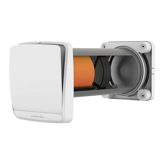
- Page 3 INHALT 1 – Frontale Klappe für das Abdeckgitter 7 – Keramik-Wärmetauscher 2 – Abdeckgitter 8 – Filter 3 – Haupteinheit 9 – Handbuch für Installation und Instandhaltung 4i – Befestigung für die Innenwand mit elektrischen Anschlüssen 10 – Allgemeine Hinweise 4e –...
-
Page 4: Technische Daten
TECHNISCHE DATEN Der Wohnraumlüfter ist in die Klasse II eingestuft worden. Die Schutzklasse ist IPX4. Der Wohnraumlüfter ist auf die Installation in geschlossenen Räumen ausgelegt. Die Betriebstemperaturen liegen zwischen -20 und +50 Grad Celsius, die maximale relative Luftfeuchtigkeit bei 80%. Das Design des Wohnraumlüfters wird stetig weiterentwickelt, deshalb können einige Modelle von den Beschreibungen in diesem Handbuch abweichen. -
Page 5: Installation
WIRELESS Geschwindigkeit 1 4 Spannung bei 50 Hz 220‐240Vac 220‐240Vac 220‐240Vac 220‐240Vac 220‐240Vac Leistung [W] 4,9 7,9 Leistung [m3/h] 30 37,5 52,5 Geräusch in 3 m Abstand [dB] 18 18,5 21,5 Max. Wirkungsgrad 93% 93% AUFBAU Das Produkt besteht aus einer Haupteinheit mitsamt einer Wandbefestigung, die an der Innenwand des zu belüftenden Raums angebracht wird, aus einem Einbaurohr, in dem der Wärmetauscher aus Keramik und die Filter angebracht sind sowie einer externen Wetterschutzabdeckung mitsamt einer Wandbefestigung... -
Page 6: Montage
1. MONTAGE Nachdem der genaue Ort der Montage ausgewählt worden ist, muss der Mittelpunkt des Bohrloches an der Wand eingezeichnet werden, durch das später das Einbaurohr geführt wird. Stellen Sie sicher, dass es rund um den Mittelpunkt des Bohrloches, sei es an der Außen-, sei es an der Innenwand im Umkreis von 15 cm keinerlei Hindernisse gibt. - Page 7 Das Rohr muss, wenn nötig, an die Wandstärke angepasst werden, und zwar mit geeigneten Werkzeugen, wie dies das folgende Schaubild zeigt. M=500mm Hat man die Länge des Einbaurohres (6) an die Wandstärke angepasst, muss die Befestigung für die Außenwand (4e) an der Außenmauer angebracht werden, wie dies im folgenden Schaubild dargestellt ist.
- Page 8 Bohren Sie die Löcher für die Befestigung und bringen Sie die vorgesehenen Dübel an. Schrauben Sie die Befestigung für die Außenwand (4e) an der Mauer fest. Lassen Sie die Abdeckung (5) wie im folgenden Schaubild gezeigt in die Befestigung für die Außenwand (4e) einrasten.
- Page 9 Gleich wie an der Außenwand müssen die Bohrlöcher für die Befestigung auch an der Innenwand markiert werden. Dafür muss der Passring der Befestigung für die Innenwand (4i) in das Einbaurohr (6) eingepasst werden, wie es obige Abbildung zeigt. Mit Hilfe einer Wasserwaage können dann die vier Bohrlöcher für die Befestigung an der Innenwand (4i) eingezeichnet werden.
- Page 10 Verbinden eines Stromkabels, aus der Wand kommend: Nach dem Einsetzen der Dübel, bevor Sie mit der Montage fortfahren, entfernen Sie den Klemmenblock aus der Halterung (4) und führen Sie die Kabel durch die entsprechende Führung. VERBINDUNG EINES KABELS VON AUSSEN AN DAS GEHÄUSE: Brechen Sie die Einkerbung wie unten ersichtlich aus Entfernen Sie den Klemmenblock aus der Halterung (4) und führen Sie die Kabel durch die entsprechende Führung.
- Page 11 2. a) Modell SOLO DIREKTER ANSCHLUSS Bevor Sie fortfahren, stellen Sie sicher, dass die Netzkabel (Leiter und Neutralleiter) bis zur dafür vorgesehenen Aussparung gezogen worden sind. Nehmen Sie die Befestigung für die Innenwand (4i) sowie alle notwendigen Werkzeuge zur Hand, um die Netzkabel an die mitgelieferten abisolierten Kabel in der vorgesehenen Aussparung anzuschließen.
- Page 12 Um die Geschwindigkeit über einen Wandschalter regulieren zu können, müssen die beiden Schalterausgänge – wie im Schaubild gezeigt – mit „S1“ und „S2“ verbunden werden. 12 ...
- Page 13 2. b) Modell ADVANCED STROMANSCHLUSS Bevor Sie fortfahren, stellen Sie sicher, dass die Netzkabel (Leiter und Neutralleiter) bis zur dafür vorgesehenen Aussparung gezogen worden sind. Nehmen Sie die Befestigung für die Innenwand (4i) sowie alle notwendigen Werkzeuge zur Hand, um die Netzkabel an die mitgelieferten abisolierten Kabel in der vorgesehenen Aussparung anzuschließen.
- Page 14 KOMMUNIKATION MIT NACHGESCHALTETEN PRODUKTEN Falls vorgesehen ist, dass mit der Haupteinheit eines oder mehrere nachgeschaltete Produkte verbunden werden, oder bereits jetzt die Anschlüsse für künftige solche Geräte geschaffen werden sollen, können alle Anleitungen dem folgenden Schaubild entnommen werden. Eine solche Anordnung ermöglicht die Kommunikation zwischen der Haupteinheit und allen nachgeschalteten Geräten.
- Page 15 MASTER-SLAVE-KONFIGURATION BEIM MODELL ADVANCED Um das Gerät, das als MASTER dienen soll, zu konfigurieren, muss dieses zunächst über den Hauptschalter „0/1“ eingeschaltet werden. Findet das Gerät kein eingeschaltetes nachgeschaltetes Produkt auf C1 oder C2, konfiguriert es sich automatisch als MASTER, und zwar innerhalb von 10 Sekunden nachdem die rote LED-Leuchte stabil leuchtet.
- Page 16 2. c) Modell WIRELESS STROMANSCHLUSS Bevor Sie fortfahren, stellen Sie sicher, dass die Netzkabel (Leiter und Neutralleiter) bis zur dafür vorgesehenen Aussparung gezogen worden sind. Achtung: Sollen mehrere Geräte in einer MASTER-SLAVE-Konfiguration nachgeschaltet werden, darf der Abstand von 20m zwischen den Geräten nicht überschritten werden. Nur die Einhaltung dieses Höchstabstandes garantiert eine einwandfreie Funktion.
- Page 17 MASTER-SLAVE-KONFIGURATION BEIM MODELL WIRELESS Für die MASTER-SLAVE-Konfiguration des Modells Wireless wird auf die Bedienungsanleitung der Fernbedienung verwiesen. 3. ABSCHLUSS DER MONTAGE Nach Abschluss der elektrischen Anschlussarbeiten müssen die Kabel vorsichtig in der vorgesehenen Aussparung untergebracht werden. Erst danach kann die Befestigung für die Innenwand (4i) mit den vier Schrauben an der Wand festgeschraubt werden, wie dies die folgende Abbildung zeigt.
-
Page 18: Wartung
WARTUNG Alle Wartungsarbeiten am Gerät sind ausschließlich qualifiziertem Fachpersonal vorbehalten. Versichern Sie sich, dass während der Wartungsarbeiten am Gerät im Netz im betroffenen Raum kein Strom fließt. Einmal installiert, muss das Produkt so aufgebaut sein, wie dies im obigen Schaubild veranschaulicht wird. - Page 19 2. SÄUBERUNG VON FILTERN UND WÄRMETAUSCHER Nehmen Sie die Haupteinheit (1+2+3) von der Wand ab, indem Sie mit Hilfe eines Schlitzschraubenziehers den unten mittig angebrachten Haken nach oben drücken (siehe Abbildung). Hat sich die Haupteinheit einmal von der Befestigung für die Innenwand (4i) gelöst, muss sie mit beiden Händen aus der Halterung gezogen werden (siehe Abbildung).
- Page 20 Nehmen Sie die Filter (8) aus ihrer Halterung und säubern Sie diese zuerst mit Hilfe eines Staubsaugers oder mit fließendem Wasser vom Staub. Bevor sie wieder eingesetzt werden, müssen die Filter komplett getrocknet sein. Sollten die Filter (8) verbraucht sein (in der Regel nach rund zwei Jahren) sollten sie durch neue ersetzt werden, die man im Handel erhält.
- Page 21 Sind die Filter (8) sauber und trocken, müssen sie wieder in ihre entsprechenden Halterungen auf dem Wärmetauscher (7) eingesetzt werden. Die Aussparungen der Filter umfassen dabei die Schnur (siehe Abbildung): 21 ...
- Page 22 3. REINIGUNG ABDECKGITTER UND VENTILATOR Nachdem Filter und Wärmetauscher gesäubert worden sind, müssen sie wieder am vorgesehenen Platz in der Mitte des Einbaurohres positioniert werden. Danach nimmt man die Haupteinheit (1+2+3) zur Hand und die frontale Klappe (1) ab, indem zuerst die oberen, dann die unteren Haken gelöst werden. Mit Hilfe eines Schlitzschraubenziehers löst man auch die Haltezähne des Abdeckgitters (2) und kann dieses von der Haupteinheit (3) lösen.
- Page 23 4. WIEDERHERSTELLUNG DES GERÄTES NACH DER REINIGUNG Setzen Sie die Haupteinheit (3) gemeinsam mit dem Abdeckgitter (2) und der frontalen Klappe (1) wieder auf die Befestigung für die Innenwand (4i). ACHTUNG: Sollten mehrere Geräte gleichzeitig gereinigt werden, achten Sie darauf, dass jede Haupteinheit wieder in das Gerät eingesetzt wird, aus dem sie entfernt worden ist.
- Page 24 ANLEITUNGEN FÜR EINE KORREKTE FUNKTIONSWEISE VERSION SOLO Geschwindigkeits-Auswahl (1/2) Hauptschalter (0/1) 1. Einschalten Nachdem das Gerät von qualifiziertem Fachpersonal montiert worden ist, muss es mit Hilfe des Hauptschalters „0/1“ an der Seite der Haupteinheit eingeschaltet werden. Stellen Sie sicher, dass die Leuchtanzeige sich eingeschaltet hat. Wird das Abdeckgitter geöffnet, beginnt das Gerät, normal zu funktionieren und im 70-Sekunden- Rhythmus zwischen Ab- und Ansaugen der Luft zu wechseln.
-
Page 25: Problembehandlung
VERSION ADVANCED UND WIRELESS Hauptschalter (0/1) Sollte man über nur ein Gerät verfügen, wird dieses über den Hauptschalter „0/1“ eingeschaltet. Danach erfolgt die Steuerung über die Fernbedienung. Sollte man mehrere Geräte in Reihe geschaltet haben, erfährt man alles Wissenswerte dazu im Kapitel „KOMMUNIKATION MIT NACHGESCHALTETEN PRODUKTEN“. - Page 26 INTRODUZIONE Questo manuale tecnico contiene descrizioni tecniche, operazioni di installazione, montaggio, manutenzione e dati tecnici esclusivamente rivolti al personale qualificato addetto alla installazione e manutenzione del prodotto. DESTINAZIONE D’USO Il prodotto è costruito a regola d’arte e viene installato per dare la possibilità di un ricambio costante di aria all’interno della stanza. Il recuperatore può essere installato in abitazioni e luoghi ...
- Page 27 CONTENUTO 7‐ Scambiatore ceramico 1‐ Frontale estetico copertura serranda 8‐ Filtri 2‐ Serranda 9‐ Manuale installazione e manutenzione 3‐ Unità principale 4i‐ Fissaggio a parete interno con connessioni 10‐ Avvertenze generali elettriche 11‐ Foglio di garanzia RAEE 4e‐ Fissaggio a parete esterno 12‐ Imballo prodotto 5‐ Convogliatore esterno 13‐ Avvertenza estrazione prodotto 6‐ Tubo da incasso 500mm 4 ...
-
Page 28: Parametri Tecnici
PARAMETRI TECNICI Il recuperatore è classificato come prodotto di Classe II. Il grado di protezione è IPX4. Il recuperatore è stato progettato per installazioni in luoghi chiusi. Le temperature di esercizio sono comprese tra ‐20°C e 50°C con umidità relativa massima 80%. Il design del recuperatore è in continua evoluzione, pertanto, alcuni modelli potrebbero differire da quanto descritto nel presente manuale. MISURE, MM ‐SOLO / ADVANCED / WIRELESS SOLO Velocità 1 4 Tensione a 50Hz 220‐240Vac 220‐240Vac X Potenza [W] 4,9 X Portata [m³/h] 30 X Rumore a 3 m [dB] 18 X Rendimento Max 93% ... -
Page 29: Installazione
WIRELESS Velocità 1 4 Tensione a 50Hz 220‐240Vac 220‐240Vac 220‐240Vac 220‐240Vac 220‐240Vac Potenza [W] 4,9 7,9 Portata [m³/h] 30 37,5 52,5 Rumore a 3 m [dB] 18 18,5 21,5 Rendimento Max 93% 93% COSTRUZIONE Il prodotto è costituito da un unità principale di funzionamento con attacco a parete che andrà posta all’interno del locale, un tubo da incasso contenente lo scambiatore ceramico ed i filtri, un ... - Page 30 1) MONTAGGIO Dopo aver individuato l’area nella quale si intende installare il prodotto segnare il centro del foro passante da realizzare sulla parete. Assicurarsi che, rispetto al centro del foro per il tubo di incasso, ci sia uno spazio libero sulle pareti interne ed esterne per un raggio di 15 cm dal centro, questi corrispondono all’ingombro del prodotto. Assicurarsi pertanto che all’interno di questa area non vi siano interferenze con pareti ed oggetti non removibili. Il diametro del foro da realizzare è Ø160mm Il foro ricavato nel muro deve essere passante e con un’inclinazione di 1°‐ 2° verso l’esterno. Per utilizzare il tubo da incasso in dotazione, lo spessore del muro non deve superare i 500mm. (O con prolunga fino a 3m). Per installare il prodotto, il muro destinato non può avere uno spessore inferiore ai 250mm. Una volta ricavato il foro passante nel muro posizionarne all’interno il tubo da incasso (6). Assicurarsi che la lunghezza del tubo da incasso (6) sia uguale allo spessore del muro. Il tubo deve terminare a filo con le superfici delle pareti interne ed esterne. La quota “M” non può essere inferiore a 250mm, in questo caso la parete prevista non è consona all’installazione del prodotto. 7 ...
- Page 31 Adattare il tubo, se necessario, allo spessore della parete con strumenti adatti, in maniera opportuna, come indicato di seguito: M=500mm Una volta adattata la lunghezza del tubo da incasso (6) allo spessore esatto della parete, posizionare il particolare attacco a parete esterno (4e) sulla parete esterna come da immagine riportata di seguito: ...
- Page 32 COLLEGAMENTO DI UN CAVO DI ALIMENTAZIONE PROVENIENTE DAL MURO: Una volta inseriti i tasselli, prima di procedere con il fissaggio, estrarre la morsettiera dal particolare fissaggio a parete interno (4i) e far passare i cavi attraverso l’apposita sede. COLLEGAMENTO DI UN CAVO DI ALIMENTAZIONE ESTERNO: Rompere le linguette di plastica indicate nelle immagini sottostanti.
-
Page 33: Collegamenti Elettrici
Realizzare i fori ed inserire i tasselli per il fissaggio a parete. Avvitare il particolare attacco a parete esterno (4e) al muro esterno. Fissare a scatto sull’attacco a parete esterno (4e) il convogliatore esterno (5) come da immagini riportate: 2) COLLEGAMENTI ELETTRICI L’installazione dell’apparecchio è destinata solo ed esclusivamente a personale qualificato. Assicurarsi che la tensione di alimentazione del locale di installazione sia conforme all’alimentazione dichiarata sulla targa dati del prodotto. Assicurarsi che il collegamento di rete nel locale di installazione venga disconnesso prima delle operazioni elettriche di montaggio. - Page 34 Come per il tracciamento dei fori esterni, inserire prima il diametro di centraggio del particolare attacco a parete interno (4i) all’interno del tubo da incasso (6) come da immagine sopra riportata. Con l’aiuto di uno strumento di misura di livello tracciare e realizzare i 4 fori per il fissaggio a parete del particolare attacco a parete interno (4i). A differenza del fissaggio a parete esterno, sulla parete interna è necessario portare i conduttori di alimentazione da connettere ai cavi spelati forniti insieme al prodotto. Ricavare, in corrispondenza della zona evidenziata, l’uscita dei cavi dalla parete. Una volta inseriti i tasselli prima di procedere con il fissaggio eseguire il collegamento elettrico a seconda della versione in vostro possesso. 10 ...
- Page 35 2a) VERSIONE SOLO COLLEGAMENTO DIRETTO Prima di procedere con il collegamento è necessario che i cavi di alimentazione (linea e neutro) siano presenti in corrispondenza della zona appositamente ricavata nella parete. Munirsi del particolare fissaggio a parete interno (4i) e degli attrezzi necessari a connettere la rete di alimentazione ai conduttori spelati forniti nell’apposito scompartimento. ...
- Page 36 Per comandare le velocità tramite interruttore da incasso collegare i due terminali dell’interruttore ai capi “S1” ed “S2” come illustrato. 12 ...
- Page 37 2b) VERSIONE ADVANCED COLLEGAMENTO ALIMENTAZIONE Prima di procedere con il collegamento è necessario che i cavi di alimentazione (linea e neutro) siano presenti in corrispondenza della zona appositamente ricavata nella parete. Munirsi del particolare fissaggio a parete interno (4i) e degli attrezzi necessari a connettere la rete di alimentazione ai conduttori spelati forniti nell’apposito scompartimento. Connettere in maniera opportuna e sicura i cavi di alimentazione della rete ai cavi provenienti dalla morsettiera. Indicazione “N” ed “L”. ...
- Page 38 COMUNICAZIONE CON PRODOTTI SLAVE Se è stato preventivato di installare uno o più prodotti in cascata all’unità principale o si intende predisporre la connessione per un futuro collegamento si faccia riferimento alle immagini di seguito per permettere la comunicazione tra l’unità principale ed i prodotti in cascata. Si consiglia di utilizzare diversi colori di cavi per evitare di invertire i collegamenti. Attenzione: è necessario rispettare il collegamento tra i segnali S1‐C1 ed S2‐C2 per evitare che si verifichino danni all’apparato elettronico COLLEGAMENTO INTERFACCIA PANNELLO REMOTO PER VERSIONE ADVANCED Nel caso si disponga dell’accessorio opzionale “pannello remoto” o nel caso si intenda prevedere il collegamento per l’acquisto dell’accessorio in un secondo momento è necessario, come riportato nell’immagine di seguito, connettere all’unità master due cavi ai terminali “C¹” e “C²” che dovranno essere poi connessi ai terminali dell’accessorio. Istruzioni specifiche di installazione “pannello remoto” presenti all’interno della scatola dell’apparecchio. ...
- Page 39 CONFIGURAZIONE PRODOTTI MASTER – SLAVE VERSIONE ADVANCED Per configurare il prodotto che si vuole utilizzare come unità MASTER, procedere con l’accensione dello stesso tramite interruttore principale “0/1” e, una volta alimentato, se non ha nessun prodotto collegato e acceso su C1 e C2, questo si configurerà come MASTER dopo i primi 10 sec in cui il led rosso rimarrà fisso. Una volta che il led rosso si spegne premere “AUTO”, se il led dà il segnale rispettivo della modalità AUTO il prodotto è configurato correttamente come MASTER. Soltanto una volta che il prodotto è identificato come unità principale MASTER è possibile iniziare la configurazione dello SLAVE1. NON INVIARE ALCUN COMANDO DA REMOTO AI PRODOTTI SLAVE Assicurarsi ...
- Page 40 2c) VERSIONE WIRELESS COLLEGAMENTO ALIMENTAZIONE Prima di procedere con il collegamento è necessario che i cavi di alimentazione (linea e neutro) siano presenti in corrispondenza della zona appositamente ricavata nella parete. Attenzione: in caso di installazione di più prodotti in configurazione MASTER‐SLAVE, al fine di ottenere una comunicazione ottimale tra le varie unità, assicurarsi di mantenere una distanza massima di 20 m tra un apparecchio e l’altro. Il tipo di materiale della muratura (es. mattoni, cemento armato), può influire sulla distanza. ...
- Page 41 CONFIGURAZIONE PRODOTTI MASTER – SLAVE VERSIONE WIRELESS Per la configurazione MASTER‐SLAVE della versione Wireless si rimanda ai paragrafi dedicati nel libretto d’istruzioni del telecomando. 3) CONCLUSIONE DEL MONTAGGIO Al termine del collegamento elettrico sistemare i fili accuratamente nel vano predisposto e avvitare il particolare a parete (4i) con le 4 viti previste come da immagine di seguito. Una volta avvitato a parete il particolare (4i), inserire lo scambiatore ceramico (7) con i relativi filtri (8), posizionandolo a metà del tubo da incasso (6) come da immagine di seguito: Fissare a scatto l’unità principale (3), insieme ai componenti serranda (2) e frontale estetico (1) già montati su di essa, nell’apposito attacco a parete (4i) fino all’aggancio di tutti i denti. Assicurarsi di installare a muro l’unità principale ponendo gli interruttori in alto, a sinistra. 17 ...
-
Page 42: Manutenzione
MANUTENZIONE Tutte le operazioni di manutenzione dell’apparecchio sono destinate solo ed esclusivamente a personale qualificato. Assicurarsi che il collegamento di rete nel locale di installazione venga disconnesso prima delle operazioni di manutenzione. Una volta installato, il prodotto deve riportare la disposizione dei componenti come da immagine sopra riportata. 1) INDICAZIONE PERIODO DI MANUTENZIONE Si consiglia la pulizia dei filtri (8) e dello scambiatore ceramico (7) ogni 3 mesi. Si consiglia il cambio dei filtri ogni 2 anni. Contattare il rivenditore per ricevere i filtri di ricambio. 1a) VERSIONE SOLO Questa versione non prevede l’allarme relativo alla pulizia/sostituzione filtri. 1b) VERSIONE ADVANCED Ogni 2000 ore di funzionamento il prodotto interrompe il suo lavoro e l’indicatore luminoso posto in basso a destra emetterà un segnale luminoso rosso continuo. Eseguire ... - Page 43 2) PULIZIA FILTRI E SCAMBIATORE Estrarre l’unità principale (1+2+3) dalla parete utilizzando un cacciavite piatto per azionare il gancio posto nella parte inferiore centrale del prodotto come illustrato di seguito. Una volta che l’unità funzionante si è sganciata dall’attacco a parete (4i) estrarla con le mani tirando energicamente come da immagine di seguito: Estrarre lo scambiatore ceramico insieme ai filtri (8+7+8), tirando verso di se l’apposita corda come da immagine di seguito. ...
- Page 44 Rimuovere i filtri (8) dalla loro sede e pulirli aspirando i residui di sporco tramite un aspirapolvere o lavandoli con acqua corrente, asciugandoli accuratamente prima di riposizionarli. Nel caso i filtri (8) risultino usurati (periodo indicativo 2 anni) cambiarli richiedendoli nuovi al rivenditore. Durante le operazioni di pulizia/sostituzione dei filtri(8), aspirare anche eventuali residui di sporco nello scambiatore ceramico. NON LAVARE LO SCAMBIATORE CERAMICO CON ACQUA. 20 ...
- Page 45 Una volta realizzate le operazioni di pulizia posizionare i filtri (8) nella loro sede sullo scambiatore (7) inserendo gli spacchi dei filtri sotto alla corda come da immagine di seguito: 21 ...
- Page 46 3)PULIZIA SERRANDA E VENTOLA Dopo aver effettuato la pulizia dei filtri e dello scambiatore riposizionarli nella loro sede. Prendere il gruppo unità principale (1+2+3) ed estrarre il particolare copertura estetica (1) estraendo prima i ganci superiori e di seguito quelli inferiori. Attraverso un cacciavite piatto fare leva sui denti di aggancio della serranda (2) per estrarla dall’unità principale (3). Pulire con un panno asciutto le griglie della serranda (2) dalla polvere o da residui di sporco in genere. ...
- Page 47 4) RIPRISTINO DEL PRODOTTO DOPO LA PULIZIA Rimontare l’unità principale (3) insieme ai particolari serranda (2) e copertura estetica (1) sull’attacco a parete (4i). ATTENZIONE: Se si effettua la pulizia di più prodotti contemporaneamente, rimontare ciascuna unità principale in corrispondenza della sede da cui era stata rimossa, al fine di evitare problemi di comunicazione tra unità master e unità slave. 4a) VERSIONE SOLO E’ sufficiente reinstallare l’unità principale a parete e dare tensione al prodotto accendendolo tramite interruttore principale. ...
- Page 48 ISTRUZIONI PER IL CORRETTO FUNZIONAMENTO VERSIONE SOLO Selezione velocità (1/2) Accensione / spegnimento (0/1) 1) Accensione Una volta che il prodotto è stato installato da personale qualificato procedere alla prima accensione del prodotto posizionando l’interruttore “0/1” posto a lato dell’unità principale. Accertarsi che l’indicatore luminoso si sia acceso. Una volta che la serranda è aperta il prodotto inizia il suo funzionamento normale con ciclo di scambio 70 secondi immissione aria 70 secondi estrazione aria.
- Page 49 VERSIONI ADVANCED E WIRELESS Accensione Spegnimento (0/1) Nel caso si disponga di una sola unità, accendere il prodotto tramite interruttore “0/1” e di seguito premere un comando da remoto per attivare il funzionamento del prodotto secondo il comando inviato. Nel caso si disponga di più unità, vedere il paragrafo “CONFIGURAZIONE PRODOTTI MASTER‐SLAVE”, una volta ultimata questa procedura accendere i prodotti tramite interruttore 0/1 e premere un comando da remoto per attivare il dispositivo. ATTENZIONE Alla prima accensione il prodotto esegue l’auto‐taratura dell’igrostato. E’ possibile che durante questa ...
-
Page 50: Intended Use
INTRODUCTION This technical manual contains operating descriptions, installation processes, assembly, maintenance, and technical data addressed exclusively to qualified staff engaged in installation and maintenance of the product. INTENDED USE The product is manufactured according to the book and installed to allow for constant exchange of the room air. - Page 51 CONTENT 1. shutter's esthetic front cover 7. ceramic exchanger 2. shutter 8. filters 3. main unit 9. instructions and maintenance manual 10. general information 4i. internal wall mounting with electric connections 11. RAEE warranty leaflet 4e. external wall mounting 12. packaging 13.
-
Page 52: Technical Parameters
TECHNICAL PARAMETERS The regenerator is classified as Class II. The degree of protection is IPX4. The regenerator was designed to be installed indoors. The operating temperatures are between -20°C and 50°C with a maximum of relative humidity equal to 80%. The regenerator design is in constant evolution, therefore, some models may differ from those described in this manual. - Page 53 WIRELESS Speed 1 4 Voltage at 50Hz 220‐240Vac 220‐240Vac 220‐240Vac 220‐240Vac 220‐240Vac Power [W] 4,9 7,9 Flow rate [m³/h] 30 37,5 52,5 Noise at 3 meters [dB] 18 18,5 21,5 Max efficiency 93% 93% CONSTRUCTION The product is constituted by a main operating unit with wall joint to be placed inside the room, a recessed tube containing the ceramic exchanger and filters, an external conveyor with wall joint.
- Page 54 1) ASSEMBLY After having identified the area intended to the product installation, mark the center of the hole to be made on the wall. Make sure that, with respect to the center of the hole for the recessed tube, there is free space on the internal and external walls for a radius of 15 cm from the center - these correspond to the volume of the product.
- Page 55 Once the length of the recessed tube (6) is fitted to the exact thickness of the wall, place the particular external wall mounting (4e) on the outer wall, as shown in the image below: M=500mm Once it is centered in the tube, draw the mounting holes on the outer wall, by using the particular external wall mounting (4e) and with the help of a level measuring tool to ensure a precise installation as in the image below: Drill the holes and insert the dowels for the...
- Page 56 Connecting a power cable, coming from the wall: After inserting the anchors, before proceeding with assembly, remove the terminal block from the bracket (4) and guide the cables through the guide. CONNECTING A CABLE FROM OUTSIDE TO THE HOUSING: Break the indentation as shown below Remove the terminal block from the bracket (4) and guide the cables through the appropriate guide.
-
Page 57: Electrical Connections
Drill the holes and insert the dowels for the wall mounting. Screw the particular external wall mounting (4e) to the outer wall. Attach the external conveyor snap-lock (5) to the external wall mounting (4e), as shown in the images: ELECTRICAL CONNECTIONS The installation of the device is intended solely and exclusively to qualified personnel. - Page 58 Like in case of the tracing of outer holes, first insert the diameter of centering of the particular internal wall mounting (4i) in the recessed tube (6), as shown in the image above. With the help of a level measuring tool trace and drill the 4 holes for the wall attachment of the particular internal wall mounting (4i).
-
Page 59: Direct Connection
2a) SOLO VERSION DIRECT CONNECTION Before proceeding with connection, make sure that the power supply cables (line and neutral) are present in the area specially formed in the wall. Extract the particular internal wall mounting (4i) and the tools necessary for connecting the power supply network with the stripped wires provided in the special compartment. - Page 60 To control the speed by means of a recessed switch, connect the two terminals of the switch to the "S1" and "S2" extremities, as illustrated. 12 ...
-
Page 61: Power Supply Connection
2b) ADVANCED VERSION POWER SUPPLY CONNECTION Before proceeding with connection, make sure that the power supply cables (line and neutral) are present in the area specially formed in the wall. Extract the particular internal wall mounting (4i) and the tools necessary for connecting the power supply network with the stripped wires provided in the special compartment. - Page 62 COMMUNICATION WITH THE SLAVE PRODUCTS If you have planned to install one or more products in the main unit in cascade, or you want to provide the attack for a future connection, refer to the images below to enable communication between the main unit and the cascade products.
- Page 63 CONFIGURATION OF THE MASTER - SLAVE PRODUCTS FOR THE ADVANCED VERSION To set up the product to be used as MASTER unit, turn on the power of this by means of the main switch "0/1" and, once it is powered, if there is no product connected and switched on at C1 and C2, this will be configured as MASTER after the first 10 seconds during which the red LED indicator will remain steady.
- Page 64 2c) WIRELESS VERSION POWER SUPPLY CONNECTION Before proceeding with connection, make sure that the power supply cables (line and neutral) are present in the area specially formed in the wall. Attention: In case of installation of several products in the MASTER-SLAVE configuration, in order to achieve optimal communication between various units, make sure that the maximum distance of 20 m between one device and the other is maintained.
- Page 65 CONFIGURATION OF THE MASTER - SLAVE PRODUCTS FOR THE WIRELESS VERSION For the MASTER-SLAVE configuration of version Wireless, see the dedicated paragraphs in the remote controller instruction booklet. 3) COMPLETION OF THE ASSEMBLY At the end of the electrical connection, fix the wires carefully in the fitted compartment, and screw the particular wall mounting (4i) into the wall, with the 4 screws provided, as in the image below.
-
Page 66: Maintenance
MAINTENANCE All the device maintenance operations are intended solely and exclusively to qualified personnel. Make sure that the network connection in the place of installation is disconnected before the maintenance operations. Once the product is installed, it must represent the component arrangement as that in the image above. - Page 67 2) FILTERS AND EXCHANGER CLEANSING Pull the main unit (1+2+3) out of the wall, by using a flat screwdriver to drive the hook placed at the bottom center of the product, as shown below. Once the operating unit is unhooked from the wall mounting (4i), pull it out strongly with your hands, as in the image below: Extract the ceramic heat exchanger, together with the filters (8+7+8), by pulling the specific rope towards yourself, as in the image below:...
- Page 68 Remove the filters (8) from their location, and clean them by suctioning the dirt residues with a vacuum cleaner, or by washing them with running water and drying them carefully before replacement. In case the filters (8) are well-worn (indicative period of 2 years), replace them by requiring new ones from your dealer.
- Page 69 Once the cleansing operations are done, put the filters (8) in their place on the heat exchanger (7), by inserting the slots of the filters under the rope, as in the image below: 21 ...
- Page 70 3) SHUTTER AND FAN CLEANSING After having cleaned the filters and the heat exchanger, reposition them in their places. Take the main unit assembly (1+2+3) and the esthetic front cover (1), by pulling out the upper hooks and then the lower ones. By means of a flat screwdriver, pry on the shutter attachment teeth (2) to remove it from the main unit (3).
- Page 71 4) PRODUCT REACTIVATION AFTER CLEANSING Replace the main unit (3), together with the specific shutter (2) and the esthetic front cover (1), onto the wall mounting (4i). ATTENTION: If you clean several products at a time, replace each main unit in conformity with their initial location, in order to avoid problems of communication between master units and slave ones.
- Page 72 INSTRUCTIONS FOR PROPER OPERATION SOLO VERSION Speed selection (1/2) Switching On / Off (0/1) 1) Start up Once the product is installed by qualified personnel, proceed with the first start of the product, by turning the switch "0/1", placed on the side of the main unit, on. Make sure that the luminous indicator is on.
- Page 73 ADVANCED AND WIRELESS VERSIONS Switching On / Off (0/1) If you have one single unit, turn the product on by means of the "0/1" switch, then press a remote command to activate the product operation, according to the command given. If you have several units, see paragraph "CONFIGURATION OF THE MASTER-SLAVE PRODUCTS";...
- Page 75 via Artigiani, 14 - 39057 Appiano (Bz) ITALY info@suedwind.it www.suedwind.it...
Need help?
Do you have a question about the AMBIENTIKA SOLO and is the answer not in the manual?
Questions and answers