Advertisement
Quick Links
HART®-Ausgangstrenner
IM35-11...-Hi/24VDC
IM35-22...-Hi/24VDC
Gerätekurzbeschreibung
•
Übertragung von Stromsignalen
(0/4...20 mA)
•
IM35-11...-Hi...: einkanalig
IM35-22...-Hi...: zweikanalig
•
Nur bei Geräten mit „Ex" in der Typen-
bezeichnung:
–
Eigensicherer Ausgangskreis Ex ia,
–
Anwendungsbereich nach ATEX:
II (1) G, II (1) D, II 3 G
–
Zugelassen für Einbau in Zone 2
•
Bidirektionale HART®-Übertragung
•
Galvanische Trennung von Ausgangskreis
zu Eingangskreis und zur Versorgungs-
spannung
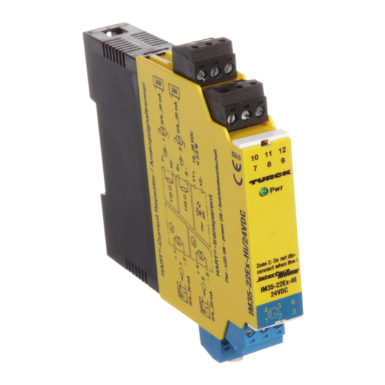
Klemmenbelegung (Fig. 2)
IM35-11...-Hi...:
1, 2
Stromausgang 1 (0/4...20 mA)
7, 10
Stromeingang 1 (0/4...20 mA)
11, 12
Betriebsspannungsanschluss
IM35-22...-Hi...:
1, 2
Stromausgang 1 (0/4...20 mA)
7, 10
Stromeingang 1 (0/4...20 mA)
4, 5
Stromausgang 2 (0/4...20 mA)
8, 9
Stromeingang 2 (0/4...20 mA)
11, 12
Betriebsspannungsanschluss
Leitungsanschluss durch anhebende Käfige
mit unverlierbaren Schrauben, Anschlussquer-
schnitt: ≤ 1 × 2,5 mm
, 2 × 1,5 mm
2
2 × 1 mm
mit Ader-Endhüsen, max. Anzugsdreh-
2
moment: 0,5 Nm
LED-Anzeige (Fig. 1)
Pwr
Betriebsbereitschaft
Fig. 1
10
11
12
7
8
9
Pwr
Zone 2: Do not dis-
connect when live!
IM35-...-Hi
24VDC
4
5
6
1
2
3
HART® Output isolator
IM35-11...-Hi/24VDC
IM35-22...-Hi/24VDC
Short description
•
Transfer of current signals (0/4...20 mA)
•
IM35-11...-Hi...: 1 channel
IM35-22...-Hi...: 2 channels
•
Only on devices with "Ex" in
the type designation:
–
Intrinsically safe output circuit Ex ia
–
Area of application acc. to ATEX:
II (1) G, II (1) D, II 3 G
–
Approved for installation in zone 2
•
Bidirectionally HART® transferring
•
Galvanic isolation of output circuit from
input circuit and from supply voltage
Terminal configuration (Fig. 2)
IM35-11...-Hi...:
1, 2
current output 1 (0/4...20 mA)
7, 10
current input 1 (0/4...20 mA)
11, 12
supply voltage connection
IM35-22...-Hi...:
1, 2
current output 1 (0/4...20 mA)
7, 10
current input 1 (0/4...20 mA)
4, 5
current output 2 (0/4...20 mA)
8, 9
current input 2 (0/4...20 mA)
11, 12
supply voltage connection
Connection via lifting cages with captive screws,
connection profile: ≤ 1 × 2.5 mm
oder
or 2 × 1 mm
2
torque: 0.5 Nm
LED indications (Fig. 1)
Pwr
power on
Fig. 2
IM35-11...-Hi...
10
11
12
7
8
9
Pwr
IM35-22...-Hi...
IM35-...Ex-Hi
24VDC
4
5
6
1
2
3
, 2 × 1.5 mm
2
with wire sleeves, max. tightening
2
HART
®
+ 1
P
– 2
I
0/4...20 mA
HART
®
+ 1
P
– 2
I
1
0/4...20 mA
HART
®
+ 4
P
– 5
I
2
0/4...20 mA
*) nur Ex-Gerät
only Ex device
seulement appareil de sécurité intrinsèque
Séparateur de sortie HART®
IM35-11...-Hi/24VDC
IM35-22...-Hi/24VDC
Description brève
•
Transmission de signaux de courant
(0/4...20 mA)
•
IM35-11...-Hi...: 1 canal
IM35-22...-Hi...: 2 canaux
•
Uniquement pour les appareils où
„Ex" figure dans la désignation de type:
– Circuit de sortie à sécurité intrin. Ex ia
– Champ d'application suivant ATEX:
II (1) G, II (1) D, II 3 G
– Certifié pour montage en zone 2
•
Transmission HART® bidirectionnelle
•
Séparation galvanique du circuit de sortie
et du circuit d'entrée entre eux et par
rapport à la tension d'alimentation
Raccordement des bornes (Fig. 2)
IM35-11...-Hi...:
1, 2
sortie de courant 1 (0/4...20 mA)
7, 10
entrée de courant 1 (0/4...20 mA)
11, 12
Raccordement de la tension de
service
IM35-22...-Hi...:
1, 2
sortie de courant 1 (0/4...20 mA)
7, 10
entrée de courant 1 (0/4...20 mA)
4, 5
sortie de courant 2 (0/4...20 mA)
8, 9
entrée de courant 2 (0/4...20 mA)
11, 12
Raccordement de la tension de
service
Raccordement du câble par des bornes à cage
levantes avec des vis imperdables, section raccor-
2
dable: ≤ 1 × 2,5 mm
, 2 × 1,5 mm
2
avec cosses, couple de serrage max.: 0,5 Nm
Visualisation par LED (Fig. 1)
Pwr
Tension de service
7 +
0/4...20 mA
110
10 –
11 +
*)
Pwr
Power
12 –
GN
7 +
0/4...20 mA
1
110
10 –
*)
8 +
0/4...20 mA
2
110
9 –
11 +
*)
Pwr
Power
12 –
GN
ou 2 × 1 mm
2
2
Advertisement

Related Manuals for turck HART IM35-11 -Hi/24VDC Series


Summary of Contents for turck HART IM35-11 -Hi/24VDC Series
- Page 1 HART®-Ausgangstrenner HART® Output isolator Séparateur de sortie HART® IM35-11…-Hi/24VDC IM35-11…-Hi/24VDC IM35-11…-Hi/24VDC IM35-22…-Hi/24VDC IM35-22…-Hi/24VDC IM35-22…-Hi/24VDC Gerätekurzbeschreibung Short description Description brève • • • Übertragung von Stromsignalen Transfer of current signals (0/4…20 mA) Transmission de signaux de courant • (0/4…20 mA) IM35-11…-Hi…: 1 channel (0/4…20 mA) •...
- Page 2 IM35-11…-Hi…/IM35-22…-Hi… Hinweis Note Conseil Aufgrund der 1:1-Übertragung werden Draht- Due to the 1:1 transfer mode a wire-break in the Dans le rapport 1:1, les ruptures de câble dans le brüche im Eingangskreis als Ausgangsstrom von input circuit is indicated by an output current of circuit d‘entrée sont disponibles comme courant 0 mA;...
- Page 3 All valid national and interna- Les données essentielles de l‘attestation d‘examen CE internationalen Bescheinigungen der TURCK-Geräte finden Sie tional approvals covering Turck devices are obtainable via the figurent au verso. L‘ensemble des certificats nationaux et Internet (www.turck.com). The special conditions of IECEx CoC im Internet (www.turck.com).
- Page 4 Irrtümer und Änderungen vorbehalten / Subject to change without notice / Sous réserve de modifications • © Hans Turck GmbH & Co. KG 2013 Hans Turck GmbH & Co. KG • Witzlebenstraße 7 • 45472 Mülheim/Ruhr • Germany • Tel. +49 208 49 52-0 • Fax +49 208 49 52-264 • more@turck.com • www.turck.com...
Need help?
Do you have a question about the HART IM35-11 -Hi/24VDC Series and is the answer not in the manual?
Questions and answers