Table of Contents
Advertisement
Quick Links
All information contained in these materials, including products and product specifications,
represents information on the product at the time of publication and is subject to change
by Midatronics S.r.l. without notice.
Doc: UG_MDX-STWBx, Rev 1.7
Document:
SHARKY - User's Guide
SHARKY I & II
User's Guide
MDX-STWBP-R01 : Sharky PCB Ant.
MDX-STWBU-R01 : Sharky uFL antenna
2020/11/18
pag. 1 of 38
Advertisement
Table of Contents

Related Manuals for Midatronics SHARKY I

Summary of Contents for Midatronics SHARKY I
- Page 1 Document: SHARKY - User’s Guide 2020/11/18 SHARKY I & II User’s Guide MDX-STWBP-R01 : Sharky PCB Ant. MDX-STWBU-R01 : Sharky uFL antenna All information contained in these materials, including products and product specifications, represents information on the product at the time of publication and is subject to change by Midatronics S.r.l.
- Page 2 Document: SHARKY - User’s Guide 2020/11/18 Outline 1. FCC Rules 1.1. List of FCC rules 2. Introduction 2.1. Description 3. System Overview 3.1. BLE Technology Overview 3.2. BLE Mesh Technology overview 3.3. Thread Technology overview 3.4. STM32WB Wireless System-on-Chip 3.5. Block Diagram 4.
- Page 3 Document: SHARKY - User’s Guide 2020/11/18 6.3. Sharky Breakout 6.3.1. Sharky PCB/uFL antenna 7. Radiation pattern plots 7.1. Sharky PCB-Ant module 8. Firmware Upload 8.1. FW upload to M4 core 8.2. FW upload to M0+ core 9. Software Development 10. References and Useful Links 10.1.
- Page 4 2020/11/18 Changes for FCC Final info@midatronics.com Disclaimer All rights strictly reserved. Reproduction in any form is not permitted without written authorization from Midatronics S.r.l. info@midatronics.com Midatronics S.r.l. www.midatronics.com Via Zucchi 1 20900 Monza (Monza Brianza) Italy Doc: UG_MDX-STWBx, Rev 1.7...
-
Page 5: Fcc Rules
“single modular transmitter”. The Midatronics SHARKY Modular Transmitter is also compliant to FCC Part 15.247 insofar as it is a device using a wide band modulation inside the band 2400-2483.5 MHz with a 6dB bandwidth greater than 500kHz. - Page 6 Document: SHARKY - User’s Guide 2020/11/18 Main features ● Module size 16.1 x 27.3 mm ● Module with: ○ PCB antenna ○ uFL antenna connector ● Integrated BLE/OpenThread or IEEE 802.15.4 programmable networking stacks Doc: UG_MDX-STWBx, Rev 1.7 pag. 6 of 38...
-
Page 7: System Overview
Document: SHARKY - User’s Guide 2020/11/18 3. System Overview 3.1. BLE Technology Overview Bluetooth Low Energy (BLE) is the main feature of the Bluetooth specification v4.0 released in December 2009. BLE is a new protocol that allows for long-term operation of Bluetooth devices that transmit low volumes of data. - Page 8 Document: SHARKY - User’s Guide 2020/11/18 Figure 2. BLE Star-bus Topology While BLE inherits the operating spectrum and the basic structure of the communication protocol from the classic Bluetooth protocol, BLE implements a new lightweight Link Layer that provides ultra-low power idle mode operation, fast device discovery, and reliable and secure point-to-multipoint data transfers.
- Page 9 Document: SHARKY - User’s Guide 2020/11/18 3.2. BLE Mesh Technology overview Figure 3. BLE Mesh Topology Borrowing from the original Bluetooth specification, the Bluetooth SIG defines several profiles — specifications for how a device works in a particular application — for low energy devices. Manufacturers are expected to implement the appropriate specifications for their device in order to ensure compatibility.
- Page 10 Document: SHARKY - User’s Guide 2020/11/18 To be able to connect these different publishers and subscribers, a mesh topology is created. The standard uses BLE advertising and scanning as an underlying technology to implement communication. To communicate in a Bluetooth Mesh network, a flooding mechanism is used. By default, a flooding mechanism ensures that each node in the network repeats incoming messages, so that they are relayed further, until the destination node is reached.
- Page 11 Document: SHARKY - User’s Guide 2020/11/18 tablet, or computer. Product installation codes are used to ensure only authorized devices can join the network. The simple protocols for forming and joining networks allow systems to self-configure and fix routing problems as they occur. ●...
- Page 12 Document: SHARKY - User’s Guide 2020/11/18 3.4. STM32WB Wireless System-on-Chip The Sharky modules are based on STMicroelectronics STM32WB55CE, a dual-core MCUs with wireless support are based on an Arm® Cortex®-M4 core running at 64 MHz (application processor) plus an Arm® Cortex®-M0+ core at 32 MHz (network processor). The STM32WB platform is an evolution of the well-known market-leading STM32L4 ultra-low-power series of MCUs.
- Page 13 Document: SHARKY - User’s Guide 2020/11/18 Figure 5. STM32WB55CE pinout Doc: UG_MDX-STWBx, Rev 1.7 pag. 13 of 38...
-
Page 14: Block Diagram
Document: SHARKY - User’s Guide 2020/11/18 3.5. Block Diagram STM32WB55CE DC/DC KByte KByte Flash SRAM IPCC PCB Antenna or uFL connector 32.7 Networking Application Stack AES2 Front Cortex Cortex USART Figure 6. Sharky Module with PCB Antenna / or uFL connector Doc: UG_MDX-STWBx, Rev 1.7 pag. - Page 15 Document: SHARKY - User’s Guide 2020/11/18 4. Connectors The following picture shows the connectors of the three Sharky types. The following MCU pins are used internally and not exposed in connector: NAME/FUNCTION Connected to: PC14-OSC32_IN 32.768 KHzquartz oscillator PC15-OSC32_OUT 32.768 KHz quartz oscillator OSC_IN 32 MHz quartz oscillator OSC_OUT...
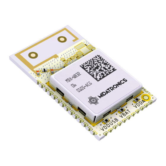
- Page 16 Document: SHARKY - User’s Guide 2020/11/18 4.1. Sharky Module Figure 8. Sharky Module pinout Doc: UG_MDX-STWBx, Rev 1.7 pag. 16 of 38...
- Page 17 Document: SHARKY - User’s Guide 2020/11/18 Sharky SoC Pin STM32WB55CE I/O COMP1_OUT, CM4_EVENTOUT, EXT_PA_TX LPUART1_RTS_DE, LPTIM2_IN1, CM4_EVENTOUT CM4_EVENTOUT FT_fla LPTIM1_IN2, TIM1_BKIN, I2C1_SDA, USART1_RX, TSC_G2_IO4, LCD_SEG21, TIM17_CH1N, CM4_EVENTOUT, COMP2_INM, PVD_IN PA14 FT_l JTCK-SWCLK, LPTIM1_OUT, I2C1_SMBA, LCD_SEG5, SAI1_FS_B, CM4_EVENTOUT PA10 FT_fl TIM1_CH3, SAI1_PDM_DI1, I2C1_SDA, USART1_RX, USB_CRS_SYNC, LCD_COM2, SAI1_SD_A, TIM17_BKIN, CM4_EVENTOUT PA15...
- Page 18 Document: SHARKY - User’s Guide 2020/11/18 BOOT0, CM4_EVENTOUT, LSCO VBAT FT_fl TIM1_CH2N, SAI1_PDM_CK1, I2C1_SCL, QUADSPI_BK1_IO1, LCD_SEG16, SAI1_MCLK_A, TIM16_CH1, CM4_EVENTOUT VDDA FT_fla TIM1_CH3N, SAI1_PDM_DI2, I2C1_SDA, SPI2_NSS, IR_OUT, TSC_G7_IO4, QUADSPI_BK1_IO0, LCD_COM3, SAI1_FS_A, TIM17_CH1, CM4_EVENTOUT FT_a TIM2_CH1, COMP1_OUT, SAI1_EXTCLK, TIM2_ETR, CM4_EVENTOUT, COMP1_INM, ADC1_IN5, RTC_TAMP2/WKUP1 FT_la TIM2_CH2, I2C1_SMBA, SPI1_SCK, LCD_SEG0,...
- Page 19 Document: SHARKY - User’s Guide 2020/11/18 CM4_EVENTOUT, ADC1_IN15 FT_fla TIM1_CH2, SAI1_PDM_DI2, I2C1_SCL, SPI2_SCK, COMP1_INM, ADC1_IN16, USART1_TX, LCD_COM1, SAI1_FS_A, CM4_EVENTOUT FT_a RTC_OUT, LPTIM1_OUT, I2C3_SMBA, SPI1_NSS, LCD_VLCD, SAI1_EXTCLK, CM4_EVENTOUT, COMP1_INP Table 2. Sharky Pinout Legend: Name Abbreviation Definition Supply Pin Input only pin Input / output pin 5 V tolerant I/O 3.6 V tolerant I/O...
-
Page 20: Power Supply
Document: SHARKY - User’s Guide 2020/11/18 5. Usage This chapter describes how to connect, configure and interact with the Sharky and Sharky Pro modules. 5.1. Power Supply Sharky and Sharky PRO modules are powered by: ● VCC/VDD pins, from 1.71 V to 3.6 V ●... - Page 21 Document: SHARKY - User’s Guide 2020/11/18 5.2. Sharky Connections 5.2.1. Power Supply on module configuration In the Sharky module VBAT, VDDA and VDDUSB can be connected to VCC soldering 0402 size, zero ohm resistors on the module. Figure 10: VBAT VDDA and VDDUSB connections on module The resistor are reachable on Sharky PCB and can be soldered to connect the pin to VCC: Figure 11: VDDUSB, VBAT and VDDA resistors placement (left side of PCB) Doc: UG_MDX-STWBx, Rev 1.7...
- Page 22 Document: SHARKY - User’s Guide 2020/11/18 5.2.2. Power Supply Figure 12: Sharky power supply connections VDD, VDDUSB and VBAT must be connected to power supply. Optionally VDDA can be connected to power supply or to an external AVDD level. 5.2.3. Reset Circuit Reset pin is already pulled up internally in the STM32WB.
- Page 23 Document: SHARKY - User’s Guide 2020/11/18 5.2.4. Boot0 pin Figure 13: Sharky boot0 pin connection Boot0 pin must be tied to ground at boot when programming with ST-Link. It can also be used as user button after boot. Boot0 pin s already connected to ground in the Sharky module, so R2 can be not populated. If you do not use the bootloader you can leave the pin disconnected.
- Page 24 Document: SHARKY - User’s Guide 2020/11/18 5.2.5. SWD - JLink-V3SET connection In the following circuit you can see the mapping to the cable adapter that is in the JLink-V3SET package: Figure 14: Sharky JLink connection Figure 15: Sharky JLink with connection cable Doc: UG_MDX-STWBx, Rev 1.7 pag.
- Page 25 Document: SHARKY - User’s Guide 2020/11/18 5.3. STLink-V3SET expansion board STLink-V3SET is composed by two boards: ● MB1440B main board ● MB1441B expansion board (optional) If the expansion board is plugged in the main board, the connector CN6 can be used to connect to the Sharky board debugging signal.
-
Page 26: Operating Conditions
Document: SHARKY - User’s Guide 2020/11/18 5.4. Operating Conditions Working temperature range: -40 to 85°C Junction temperature range: -40 to 105 °C Working relative humidity range: 20 to 80% Power Supply: 1.71 to 3.6 V USB supply voltage, USB used: 3.0 to 3.6 V Doc: UG_MDX-STWBx, Rev 1.7 pag. -
Page 27: Board Layout
Document: SHARKY - User’s Guide 2020/11/18 6. Board Layout The following pictures show the dimensions of the three Sharky types. 6.1. Sharky Module Figure 22. Sharky Module dimensions with PCB or uFL antenna Doc: UG_MDX-STWBx, Rev 1.7 pag. 27 of 38... -
Page 28: Mounting Suggestions
Document: SHARKY - User’s Guide 2020/11/18 6.2. Mounting Suggestions The module must be placed on host board, the printed antenna area must not overlap with the carrier board. The portion of the module containing the antenna should stick out over the edge of the host board. - Page 29 Document: SHARKY - User’s Guide 2020/11/18 6.2.1. Sharky PCB Antenna Figure 25. Sharky Module Mounting for PCB Antenna The Sharky module must be mounted leaving the antenna section of the PCB outside the host PCB ad in Figure 15. In this configuration, it is necessary to keep the output power of the last Bluetooth channel (2480MHz) below 1dBm for regulatory limits.
- Page 30 Document: SHARKY - User’s Guide 2020/11/18 6.2.2. Sharky uFL Antenna The Sharky uFL antenna module has no particular requirements for board placement. Keep the large metal objects away from antenna to avoid electromagnetic field blocking.• Do not enclose the antenna within a metal shield. Keep any components which may radiate noise or signals within the 2.4 GHz –...
- Page 31 Document: SHARKY - User’s Guide 2020/11/18 6.3. Sharky Breakout 6.3.1. Sharky PCB/uFL antenna Figure 28. Sharky Module Breakout for Sharky PCB antenna and uFL Antenna Part number for ordering with module soldered: MDX-BRK-STWBP-R01 : with PCB antenna module MDX-BRK-STWBU-R01 : with uFL antenna module Doc: UG_MDX-STWBx, Rev 1.7 pag.
- Page 32 Document: SHARKY - User’s Guide 2020/11/18 7. Radiation pattern plots 7.1. Sharky PCB-Ant module Figure 31. Sharky PCB Antenna radiation pattern Doc: UG_MDX-STWBx, Rev 1.7 pag. 32 of 38...
-
Page 33: Firmware Upload
Document: SHARKY - User’s Guide 2020/11/18 8. Firmware Upload The STM32WB SoC inside the Sharky module has 2 cores that share the same FLASH and SRAM addresses: ● M0+ core for embedded communication stack ● M4 core for user application The module is delivered with BLE communication stack firmware installed on M0+ core and Transparent VCP firmware on M4 core. - Page 34 Document: SHARKY - User’s Guide 2020/11/18 ● stm32wb5x_Thread_FTD_fw.bin ○ Full Thread Device certified v1.1 ○ To be used for Leader / Router / End Device Thread role (full features excepting Border Router) ● stm32wb5x_Thread_MTD_fw.bin ○ Minimal Thread Device certified v1.1 ○...
-
Page 35: Software Development
Document: SHARKY - User’s Guide 2020/11/18 9. Software Development The firmware can be developed and uploaded with STLink V2 or V3 device using the integrated provided that downloaded from https://www.st.com/en/development-tools/stm32cubeide.html The developed application runs on the M4 core and interfaces to the communication stack on M0+ core using the communication functions provided by ST . -
Page 36: References And Useful Links
● https://www.st.com/content/st_com/en/products/microcontrollers- microprocessors/stm32-32-bit-arm-cortex-mcus/stm32-wireless-mcus/stm32wb- series/stm32wbx5/stm32wb55ce.html ● https://www.st.com/resource/en/datasheet/stm32wb55ce.pdf ● https://www.st.com/resource/en/reference_manual/dm00318631.pdf ● https://www.st.com/resource/en/programming_manual/dm00046982.pdf 10.2. Tools ● https://www.st.com/en/development-tools/stm32cubeide.html ● https://www.st.com/en/development-tools/stm32cubeprog.html ● https://www.st.com/en/development-tools/stm32cubemx.html ● https://www.st.com/en/development-tools/stm32cubemonrf.html 10.3. WebSites ● http://www.midatronics.com ● https://www.st.com 10.4. Bibliography ● http://www.summitdata.com/blog/ble-overview/ ● https://www.ncbi.nlm.nih.gov/pmc/articles/PMC6111614/ Doc: UG_MDX-STWBx, Rev 1.7 pag. 36 of 38... - Page 37 Document: SHARKY - User’s Guide 2020/11/18 11. FCC 11.1. Label and Compliance Information (FCC) A host product itself is required to comply with all other applicable FCC equipment authorization regulations, requirements, and equipment functions that are not associated with the transmitter module portion. The SHARKY module have been labeled with its own FCC ID number.
- Page 38 Document: SHARKY - User’s Guide 2020/11/18 not installed and used in accordance with the instruction manual, may cause harmful interference to radio communications. Operation of this equipment in a residential area is likely to cause harmful interference in which case the user will be required to correct the interference at his own expense.
Need help?
Do you have a question about the SHARKY I and is the answer not in the manual?
Questions and answers