Table of Contents
Advertisement
Quick Links
SHARKY - SHARKY PRO
All information contained in these materials, including products and product specifications,
represents information on the product at the time of publication and is subject to change
by Midatronics S.r.l. without notice.
Doc: UG_MDX-STWBx, Rev 1.6
Document:
SHARKY - User's Guide
User's Guide
MDX-STWBP-R01 : Sharky PCB Ant.
MDX-STWBU-R01 : Sharky uFL antenna
MDX-STWBC-R01 : Sharky Pro chip antenna
MDX-STWBW-R01 : Sharky Pro no antenna
2020/07/20
pag. 1 of 57
Advertisement
Table of Contents

Related Manuals for Midatronics SHARKY

Summary of Contents for Midatronics SHARKY
- Page 1 User’s Guide MDX-STWBP-R01 : Sharky PCB Ant. MDX-STWBU-R01 : Sharky uFL antenna MDX-STWBC-R01 : Sharky Pro chip antenna MDX-STWBW-R01 : Sharky Pro no antenna All information contained in these materials, including products and product specifications, represents information on the product at the time of publication and is subject to change by Midatronics S.r.l.
- Page 2 Document: SHARKY - User’s Guide 2020/07/20 Outline 1. FCC Rules 1.1. List of FCC rules I ntroduction 2.1. Description 3. System Overview 3.1. B LE Technology Overview 3.2. B LE Mesh Technology overview 3.3. T hread Technology overview 3.4.
- Page 3 SHARKY - User’s Guide 2020/07/20 6.4.2. S harky uFL Antenna 6.4.3. S harky Pro Chip Antenna 6.4.4. Sharky Pro external antenna 6.4.5. Sharky uFL Suggested Antennas 6.5. S harky Breakout 6.5.1. Sharky PCB/uFL antenna 6.5.2. S harky Pro Chip Antenna 6.5.3.
-
Page 4: Table Of Contents
Figure 3. BLE Mesh Topology Figure 4. Thread Network Architecture Figure 5. STM32WB55CE pinout Figure 6. Sharky Module with PCB Antenna / or uFL connector Figure 7. Sharky Pro Module with Chip Antenna / no Antenna Figure 8. Sharky Module pinout Figure 9. - Page 5 Figure 26: PCB layout under chip antenna Figure 27: Recommended PCB Layout for antenna circuit Figure 28. Sharky Module Breakout for Sharky PCB antenna and uFL Antenna Figure 29. Sharky Module Breakout for Sharky Pro Chip Antenna Figure 30. Sharky Module Breakout for Sharky Pro No Antenna Figure 31.
- Page 6 Document: SHARKY - User’s Guide 2020/07/20 Tables Table 1. Module internal pins Table 2. Sharky Pinout Table 3. Sharky Pro pinout Table 4. SWD connector CN6 Doc: UG_MDX-STWBx, Rev 1.6 pag. 6 of 57...
- Page 7 Document: SHARKY - User’s Guide 2020/07/20 Revisions REVISION DATE DESCRIPTION STATUS AUTHOR REVISER 2019/04/04 First Release Draft info@midatronics.com UA-EM 2019/09/19 Changed chap 9 Draft info@midatronics.com UA-EM 2020/02/07 Changed chap Draft info@midatronics.com UA-EM 3.1, 4, 5, 6 2020/03/30 Added chap 4.4 Draft info@midatronics.com...
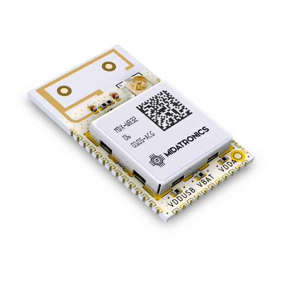
- Page 8 2.1. Description This document describes the Sharky modules. Sharky is a complete family of modules that enables customer to test and integrate the new STM32WB MCU for rapid prototyping and fast time to market. Sharky modules are based on STMicroelectronics STM32WB55CE, a dual-core MCUs with wireless support based on an Arm®...
- Page 9 Document: SHARKY - User’s Guide 2020/07/20 Sharky modules are sold standalone or soldered on a breakout board for easy connections. Main features ● Module size from 16.1 x 27.3 mm down to 14.6 x 14.6 mm ● Module with: ○ PCB antenna ○...
-
Page 10: Figure 1. Bluetooth Scatternet Topology
Document: SHARKY - User’s Guide 2020/07/20 3. System Overview 3.1. B LE Technology Overview Bluetooth Low Energy (BLE) is the main feature of the Bluetooth specification v4.0 released in December 2009. BLE is a new protocol that allows for long-term operation of Bluetooth devices that transmit low volumes of data. -
Page 11: Figure 2. Ble Star-Bus Topology
Document: SHARKY - User’s Guide 2020/07/20 Figure 2. BLE Star-bus Topology While BLE inherits the operating spectrum and the basic structure of the communication protocol from the classic Bluetooth protocol, BLE implements a new lightweight Link Layer that provides ultra-low power idle mode operation, fast device discovery, and reliable and secure point-to-multipoint data transfers. -
Page 12: Figure 3. Ble Mesh Topology
Document: SHARKY - User’s Guide 2020/07/20 3.2. B LE Mesh Technology overview Figure 3. BLE Mesh Topology Borrowing from the original Bluetooth specification, the Bluetooth SIG defines several profiles — specifications for how a device works in a particular application — for low energy devices. -
Page 13: Figure 4. Thread Network Architecture
Document: SHARKY - User’s Guide 2020/07/20 This concept is used as an inspiration for the implementation in the standard. A node in a Bluetooth Mesh network can subscribe to one or more addresses (stored in the s ubscriber list ) and publish to one specific address (stored in the p ublish address ) . - Page 14 Document: SHARKY - User’s Guide 2020/07/20 These are the general characteristics of the Thread stack focused on the Connected Home: ● Simple network installation, start-up, and operation : The Thread stack supports several network topologies. Installation is simple using a smartphone, tablet, or computer.
- Page 15 2020/07/20 3.4. S TM32WB Wireless System-on-Chip The Sharky modules are based on STMicroelectronics STM32WB55CE, a dual-core MCUs with wireless support are based on an Arm® Cortex®-M4 core running at 64 MHz (application processor) plus an Arm® Cortex®-M0+ core at 32 MHz (network processor).
-
Page 16: Figure 5. Stm32Wb55Ce Pinout
Document: SHARKY - User’s Guide 2020/07/20 Figure 5. STM32WB55CE pinout Doc: UG_MDX-STWBx, Rev 1.6 pag. 16 of 57... -
Page 17: Figure 6. Sharky Module With Pcb Antenna / Or Ufl Connector
Document: SHARKY - User’s Guide 2020/07/20 3.5. Block Diagram Figure 6. Sharky Module with PCB Antenna / or uFL connector - PRO chip Antenna Figure 7. Sharky Pro Module with no Antenna Doc: UG_MDX-STWBx, Rev 1.6 pag. 17 of 57... -
Page 18: Table 1. Module Internal Pins
Document: SHARKY - User’s Guide 2020/07/20 4. Connectors The following picture shows the connectors of the three Sharky types. The following MCU pins are used internally and not exposed in connector: NAME/FUNCTION Connected to: PC14-OSC32_IN 32.768 KHzquartz oscillator PC15-OSC32_OUT 32.768 KHz quartz oscillator... -
Page 19: Figure 8. Sharky Module Pinout
Document: SHARKY - User’s Guide 2020/07/20 4.1. Sharky Module Figure 8. Sharky Module pinout Doc: UG_MDX-STWBx, Rev 1.6 pag. 19 of 57... - Page 20 Document: SHARKY - User’s Guide 2020/07/20 Sharky SoC Pin STM32WB55CE I/O COMP1_OUT, CM4_EVENTOUT, EXT_PA_TX LPUART1_RTS_DE, LPTIM2_IN1, CM4_EVENTOUT CM4_EVENTOUT FT_fla LPTIM1_IN2, TIM1_BKIN, I2C1_SDA, USART1_RX, TSC_G2_IO4, LCD_SEG21, TIM17_CH1N, CM4_EVENTOUT, COMP2_INM, PVD_IN PA14 FT_l JTCK-SWCLK, LPTIM1_OUT, I2C1_SMBA, LCD_SEG5, SAI1_FS_B, CM4_EVENTOUT PA10 FT_fl TIM1_CH3, SAI1_PDM_DI1, I2C1_SDA, USART1_RX,...
- Page 21 Document: SHARKY - User’s Guide 2020/07/20 FT_fla LPTIM1_ETR, I2C1_SCL, USART1_TX, TSC_G2_IO3, LCD_SEG6, SAI1_FS_B, TIM16_CH1N, MCO, CM4_EVENTOUT, COMP2_INP VDDUSB BOOT0, CM4_EVENTOUT, LSCO VBAT FT_fl TIM1_CH2N, SAI1_PDM_CK1, I2C1_SCL, QUADSPI_BK1_IO1, LCD_SEG16, SAI1_MCLK_A, TIM16_CH1, CM4_EVENTOUT VDDA FT_fla TIM1_CH3N, SAI1_PDM_DI2, I2C1_SDA, SPI2_NSS, IR_OUT, TSC_G7_IO4, QUADSPI_BK1_IO0, LCD_COM3, SAI1_FS_A,...
-
Page 22: Table 2. Sharky Pinout
Document: SHARKY - User’s Guide 2020/07/20 QUADSPI_BK1_IO3, LCD_SEG3, TIM16_CH1, CM4_EVENTOUT, ADC1_IN11 FT_fla TIM1_CH1N, I2C3_SCL, SPI1_MOSI, QUADSPI_BK1_IO2, ADC1_IN12, LCD_SEG4, COMP2_OUT, TIM17_CH1, CM4_EVENTOUT FT_la MCO, TIM1_CH1, SAI1_PDM_CK2, USART1_CK, LCD_COM0, SAI1_SCK_A, LPTIM2_OUT, CM4_EVENTOUT, ADC1_IN15 FT_fla TIM1_CH2, SAI1_PDM_DI2, I2C1_SCL, SPI2_SCK, COMP1_INM, ADC1_IN16, USART1_TX, LCD_COM1,... -
Page 23: Figure 9. Sharky Pro Module Pinout
2020/07/20 4.2. Sharky Pro Module * JK and JL rows are present only in Sharky Pro Chip Antenna JH4 is antenna connection on Sharky Pro no Antenna Figure 9. Sharky Pro Module Pinout from top of module Doc: UG_MDX-STWBx, Rev 1.6... - Page 24 Document: SHARKY - User’s Guide 2020/07/20 Sharky SoC Pin STM32WB55CE I/O Pro Pin PA11 FT_u TIM1_CH4, TIM1_BKIN2, SPI1_MISO, USART1_CTS, USB_DM, CM4_EVENTOUT PA12 FT_u TIM1_ETR, SPI1_MOSI, LPUART1_RX, USART1_RTS_DE, USB_DP, CM4_EVENTOUT PA15 FT_l JTDI, TIM2_CH1, TIM2_ETR, SPI1_NSS, TSC_G3_IO1, LCD_SEG17, CM4_EVENTOUT FT_la JTDO-TRACESWO, TIM2_CH2, SPI1_SCK,...
- Page 25 Document: SHARKY - User’s Guide 2020/07/20 USB_CRS_SYNC, LCD_COM2, SAI1_SD_A, TIM17_BKIN, CM4_EVENTOUT PA13 FT_u JTMS-SWDIO, IR_OUT, USB_NOE, SAI1_SD_B, CM4_EVENTOUT VBAT FT_fl TIM1_CH2N, SAI1_PDM_CK1, I2C1_SCL, QUADSPI_BK1_IO1, LCD_SEG16, SAI1_MCLK_A, TIM16_CH1, CM4_EVENTOUT CM4_EVENTOUT FT_la MCO, TIM1_CH1, SAI1_PDM_CK2, USART1_CK, LCD_COM0, SAI1_SCK_A, LPTIM2_OUT, CM4_EVENTOUT, ADC1_IN15 FT_fla...
- Page 26 Document: SHARKY - User’s Guide 2020/07/20 FT_a TIM2_CH1, COMP1_OUT, SAI1_EXTCLK, TIM2_ETR, CM4_EVENTOUT, COMP1_INM, ADC1_IN5, RTC_TAMP2/WKUP1 FT_la TIM2_CH2, I2C1_SMBA, SPI1_SCK, LCD_SEG0, CM4_EVENTOUT, COMP1_INP, ADC1_IN6 COMP1_OUT, CM4_EVENTOUT, EXT_PA_TX FT_a RTC_OUT, LPTIM1_OUT, I2C3_SMBA, SPI1_NSS, LCD_VLCD, SAI1_EXTCLK, CM4_EVENTOUT, COMP1_INP FT_la TIM2_CH4, SAI1_PDM_CK1, LPUART1_RX, QUADSPI_CLK, LCD_SEG2, SAI1_MCLK_A,...
-
Page 27: Table 3. Sharky Pro Pinout
QUADSPI_BK1_IO2, ADC1_IN12, LCD_SEG4, COMP2_OUT, TIM17_CH1, CM4_EVENTOUT FT_a TIM2_CH1, TIM2_ETR, COMP1_INM, COMP2_INM, SPI1_SCK, LPTIM2_ETR, ADC1_IN10, SAI1_SD_B, CM4_EVENTOUT Table 3. Sharky Pro pinout Legend: These pins are present only in Sharky Pro Chip Antenna module Doc: UG_MDX-STWBx, Rev 1.6 pag. 27 of 57... - Page 28 Document: SHARKY - User’s Guide 2020/07/20 Name Abbreviation Definition Supply Pin Input only pin Input / output pin 5 V tolerant I/O 3.6 V tolerant I/O RF I/O Bidirectional reset pin with weak pull-up resistor Option for TT or FT I/Os...
- Page 29 Document: SHARKY - User’s Guide 2020/07/20 5. U sage This chapter describes how to connect, configure and interact with the Sharky and Sharky Pro modules. 5.1. P ower Supply Sharky and Sharky PRO modules are powered by: ● VCC/VDD pins, from 1.71 V to 3.6 V ●...
-
Page 30: Figure 10: Vbat Vdda And Vddusb Connections
Figure 10: VBAT VDDA and VDDUSB connections on module The resistor are reachable on Sharky PCB and can be soldered to connect the pin to VCC: Figure 11: VDDUSB, VBAT and VDDA resistors placement (left side of PCB) Doc: UG_MDX-STWBx, Rev 1.6... -
Page 31: Figure 12: Sharky Power Supply Connections
SHARKY - User’s Guide 2020/07/20 5.2.2. Power Supply Figure 12: Sharky power supply connections VDD, VDDUSB and VBAT must be connected to power supply. Optionally VDDA can be connected to power supply or to an external AVDD level. 5.2.3. R eset Circuit Reset pin is already pulled up internally in the STM32WB. -
Page 32: Figure 13: Sharky Boot0 Pin Connection
Boot0 pin must be tied to ground at boot when programming with ST-Link. It can also be used as user button after boot. Boot0 pin s already connected to ground in the Sharky module, so R2 can be not populated. If you do not use the bootloader you can leave the pin disconnected. -
Page 33: Figure 14: Sharky Jlink Connection
5.2.5. SWD - JLink-V3SET connection In the following circuit you can see the mapping to the cable adapter that is in the JLink-V3SET package: Figure 14: Sharky JLink connection Figure 15: Sharky JLink with connection cable Doc: UG_MDX-STWBx, Rev 1.6 pag. 33 of 57... -
Page 34: Figure 16: Sharky Pro Power Supply Connections
5.3. S harky Pro Connections 5.3.1. P ower Supply Figure 16: Sharky Pro power supply connections VDD, VDDUSB and VBAT must be connected to power supply. Optionally VDDA can be connected to power supply or to an external AVDD level. -
Page 35: Figure 17: Sharky Pro Boot0 Pin Connection
Boot0 pin must be tied to ground at boot when programming with ST-Link. It can also be used as user button after boot. Boot0 pin s already connected to ground in the Sharky module, so R2 can be not populated. If you do not use the bootloader you can leave the pin disconnected. -
Page 36: Figure 18: Sharky Pro Jlink Connection
In the following circuit you can see the mapping to the cable adapter that is in the JLink-V3SET package: Figure 18: Sharky Pro JLink connection Figure 19: Sharky Pro JLink with connection cable Doc: UG_MDX-STWBx, Rev 1.6 pag. 36 of 57... -
Page 37: Figure 20: Sharky Pro No Antenna - External Antenna Connection
2020/07/20 5.3.5. E xternal antenna This paragraph pertains only to Sharky Pro no Antenna module. Figure 20: Sharky Pro No Antenna - External antenna connection The H4 pin can be directly connected to an onboard antenna or connector for external antenna. -
Page 38: Figure 21. Mb1440B Main Board (Left) And Mb1441B Expansion Board (Right)
● MB1440B main board ● MB1441B expansion board (optional) If the expansion board is plugged in the main board, the connector CN6 can be used to connect to the Sharky board debugging signal. From the UM2448 ST manual: STLINK Pin N. Description Sharky Pin N. - Page 39 Document: SHARKY - User’s Guide 2020/07/20 5.5. Operating Conditions Working temperature range: -40 to 85°C Junction temperature range: -40 to 105 °C Working relative humidity range: 20 to 80% Power Supply: 1.71 to 3.6 V USB supply voltage, USB used: 3.0 to 3.6 V Doc: UG_MDX-STWBx, Rev 1.6...
-
Page 40: Figure 22. Sharky Module Dimensions With Pcb Or Ufl Antenna
SHARKY - User’s Guide 2020/07/20 6. B oard Layout The following pictures show the dimensions of the three Sharky types. 6.1. S harky Module Figure 22. Sharky Module dimensions with PCB or uFL antenna Doc: UG_MDX-STWBx, Rev 1.6... -
Page 41: Figure 23. Sharky Pro Module Dimensions With Chip Antenna
Document: SHARKY - User’s Guide 2020/07/20 6.2. S harky Pro Module with Chip Antenna Figure 23. Sharky Pro Module dimensions with Chip antenna Doc: UG_MDX-STWBx, Rev 1.6 pag. 41 of 57... -
Page 42: Figure 24. Sharky Pro Module Dimensions With No Antenna
Document: SHARKY - User’s Guide 2020/07/20 6.3. S harky Pro Module No Antenna Figure 24. Sharky Pro Module dimensions with no antenna - view from top of module Doc: UG_MDX-STWBx, Rev 1.6 pag. 42 of 57... - Page 43 Document: SHARKY - User’s Guide 2020/07/20 6.4. M ounting Suggestions The module must be placed on host board, the printed antenna area must not overlap with the carrier board. The portion of the module containing the antenna should stick out over the edge of the host board.
-
Page 44: Figure 25. Sharky Module Mounting For Pcb Antenna
6.4.1. S harky PCB Antenna Figure 25. Sharky Module Mounting for PCB Antenna The Sharky module must be mounted leaving the antenna section of the PCB outside the host PCB ad in Figure 15. In this configuration, it is necessary to keep the output power of the last Bluetooth channel (2480MHz) below 1dBm for regulatory limits. - Page 45 Document: SHARKY - User’s Guide 2020/07/20 radiated from the host board in this frequency band will degrade the sensitivity of the module. Make sure the width of the traces routed to GND, VDD and VBAT rails are sufficiently larger forhandling the peak Tx current consumption 6.4.3.
- Page 46 Document: SHARKY - User’s Guide 2020/07/20 6.4.4. Sharky Pro external antenna Figure 27: Recommended PCB Layout for antenna circuit 6.4.5. Sharky uFL Suggested Antennas Manufacturer Part Number Frequencies Specification 2J-antennae 2JP0102P WIFI / BLUETOOTH Impedance: 50 Ohm (2.4 GHz) Polarization: Linear WIFI (5.0 GHz)
- Page 47 2020/07/20 6.5. S harky Breakout 6.5.1. Sharky PCB/uFL antenna Figure 28. Sharky Module Breakout for Sharky PCB antenna and uFL Antenna Part number for ordering with module soldered: MDX-BRK-STWBP-R01 : with PCB antenna module MDX-BRK-STWBU-R01 : with uFL antenna module Doc: UG_MDX-STWBx, Rev 1.6...
- Page 48 SHARKY - User’s Guide 2020/07/20 6.5.2. S harky Pro Chip Antenna Figure 29. Sharky Module Breakout for Sharky Pro Chip Antenna Part number for ordering with module soldered: MDX-BRK-STWBC-R01 : with Sharky Pro Chip Antenna Module Doc: UG_MDX-STWBx, Rev 1.6...
- Page 49 SHARKY - User’s Guide 2020/07/20 6.5.3. S harky Pro No Antenna Figure 30. Sharky Module Breakout for Sharky Pro No Antenna Part number for ordering with module soldered: MDX-BRK-STWBW-R01 : with Sharky Pro no Antenna Module Doc: UG_MDX-STWBx, Rev 1.6...
- Page 50 Document: SHARKY - User’s Guide 2020/07/20 7. Radiation pattern plots 7.1. Sharky PCB-Ant module Figure 31. Sharky PCB Antenna radiation pattern Doc: UG_MDX-STWBx, Rev 1.6 pag. 50 of 57...
- Page 51 Document: SHARKY - User’s Guide 2020/07/20 7.2. S harky Pro Chip Antenna module Figure 32. Sharky PCB Antenna radiation pattern Doc: UG_MDX-STWBx, Rev 1.6 pag. 51 of 57...
- Page 52 SHARKY - User’s Guide 2020/07/20 8. F irmware Upload The STM32WB SoC inside the Sharky module has 2 cores that share the same FLASH and SRAM addresses: ● M0+ core for embedded communication stack ● M4 core for user application The module is delivered with BLE communication stack firmware installed on M0+ core and Transparent VCP firmware on M4 core.
- Page 53 Document: SHARKY - User’s Guide 2020/07/20 ○ To be used for Leader / Router / End Device Thread role (full features excepting Border Router) ● stm32wb5x_Thread_MTD_fw.bin ○ Minimal Thread Device certified v1.1 ○ To be used for End Device and Sleepy End Device Thread role ●...
- Page 54 The developed application runs on the M4 core and interfaces to the communication stack on M0+ core using the communication functions provided by ST . Figure 33. STM32CubeIDE from ST In order to develop a custom firmware to be uploaded to the Sharky Module the following tools are necessary: ● A Windows/Linux/MacOS PC ●...
- Page 55 Document: SHARKY - User’s Guide 2020/07/20 10. R eferences and Useful Links 10.1. Data Sheets and documents ● https://www.st.com/content/st_com/en/products/microcontrollers-microprocessors/st m32-32-bit-arm-cortex-mcus/stm32-wireless-mcus/stm32wb-series/stm32wbx5/stm3 2wb55ce.html ● https://www.st.com/resource/en/datasheet/stm32wb55ce.pdf ● https://www.st.com/resource/en/reference_manual/dm00318631.pdf ● https://www.st.com/resource/en/programming_manual/dm00046982.pdf 10.2. T ools ● https://www.st.com/en/development-tools/stm32cubeide.html ● https://www.st.com/en/development-tools/stm32cubeprog.html ● https://www.st.com/en/development-tools/stm32cubemx.html ● https://www.st.com/en/development-tools/stm32cubemonrf.html 10.3.
- Page 56 The SHARKY module have been labeled with its own FCC ID number. If the FCC ID is not visible when the module is installed inside another device, then the outside of the finished product into which the module is installed must display a label referring to the enclosed module.
- Page 57 Document: SHARKY - User’s Guide 2020/07/20 commercial environment. This equipment generates, uses, and can radiate radio frequency energy and, if not installed and used in accordance with the instruction manual, may cause harmful interference to radio communications. Operation of this equipment in a residential area is likely to cause harmful interference in which case the user will be required to correct the interference at his own expense.
Need help?
Do you have a question about the SHARKY and is the answer not in the manual?
Questions and answers