Table of Contents
Advertisement
Available languages
Available languages
Quick Links
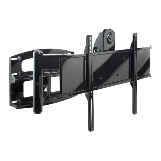
Installation and Assembly
Swivel Arm for 37" - 60" Plasma Screens
3215 W. North Ave. • Melrose Park, IL 60160 • (800) 729-0307 or (708) 865-8870 • Fax: (708) 865-2941 • www.peerlessmounts.com
- Universal Articulating
Models: PLA 60-UNL, PLA 60-UNL-S,
PLA 60-UNLP, PLA 60-UNLP-S,
PLAV 60-UNL, PLAV 60-UNL-S,
PLAV 60-UNLP, PLAV 60-UNLP-S
RTPLA 60, RTPLA 60-S, RTPLA UN7,
RTPLA UN7S, D-FPA-320, D-FPA-320S
This product is UL Listed. It must be
installed by a qualified professional
R
installer.
Maximum UL Load Capacity: 175 lb (79 kg)
ISSUED: 06-05-06 SHEET #: 202-9141-5 12-05-06
Advertisement
Table of Contents

Related Manuals for PEERLESS Mounts PLA 60-UNL


Summary of Contents for PEERLESS Mounts PLA 60-UNL
- Page 1 Models: PLA 60-UNL, PLA 60-UNL-S, Installation and Assembly - Universal Articulating PLA 60-UNLP, PLA 60-UNLP-S, Swivel Arm for 37" - 60" Plasma Screens PLAV 60-UNL, PLAV 60-UNL-S, PLAV 60-UNLP, PLAV 60-UNLP-S RTPLA 60, RTPLA 60-S, RTPLA UN7, RTPLA UN7S, D-FPA-320, D-FPA-320S This product is UL Listed.
-
Page 2: Tools Needed For Assembly
Read instruction sheet before you start installation and assembly. WARNING • Do not begin to install your Peerless product until you have read and understood the instructions and warnings contained in this Installation Sheet. If you have any questions regarding any of the instructions or warnings, please call Peerless customer care at 1-800-729-0307. -
Page 3: Wall Mount Parts List
D-FPA-320S RTPLA UN7 RTPLA UN7S RTPLA 60 RTPLA 60-S Before you start make sure all parts PLA 60-UNL PLA 60-UNL-S PLAV 60-UNL PLAV 60-UNL-S listed are included with your product. PLA 60-UNLP PLA 60-UNLP-S PLAV 60-UNLP PLAV 60-UNLP-S DESCRIPTION QTY. PART #... - Page 4 Before you b egin, make sure all parts shown are included with your product. RTPLA UN7 RTPLA UN7S RTPLA 60 RTPLA 60-S PLA 60-UNL PLA 60-UNL-S PLA 60-UNLP PLA 60-UNLP-S Adapter Bracket Parts List PLAV 60-UNL PLAV 60-UNL-S PLAV 60-UNLP PLAV 60-UNLP-S...
- Page 5 Security Adapter Bracket Fasteners M4 x 12 mm (6) M5 x 12 mm (4) M6 x 12 mm (4) 510-1079 520-1064 520-1050 M8 x 15 mm (6) M6 x 20 mm (4) 520-1068 520-9554 M5 x 25 mm (4) 520-1122 M4 x 25 mm (4) M6 x 25 mm (4) M8 x 25 mm (4)
-
Page 6: Installation To Wood Stud Wall
Place wall plate on wall as a template. The top mounting slots should be located .36" above the desired screen center for PLA 60-UNL, PLA 60-UNL-S, PLA 60-UNLP, PLA 60-UNLP-S, RTPLA 60 RTPLA 60-S and .43" below the desired screen center for PLAV 60-UNL, PLAV 60-UNL-S, PLAV 60-UNLP, PLAV 60-UNLP-S, RTPLA UN7, RTPLA UN7S, D-FPA-320, and D-FPA-320S. - Page 7 The top mounting slots should be located .36" above the desired screen center for PLA 60-UNL, PLA 60-UNL-S, PLA 60-UNLP, RTPLA 60, PLA 60-UNLP-S and RTPLA 60-S and .43" below the desired screen center for PLAV 60-UNL, PLAV 60-UNL-S, PLAV...
- Page 8 WARNING • If you are uncertain that product is properly installed, call customer care. Note: There are five mounting positions. The center position is shown (right). Slide washer (J) over wall support arm axle (D). Next, insert plastic cap (N) into axle. Then, insert holding pin (M) into axle.
- Page 9 Attach two pieces of vinyl trim (E) to wall plate (A). Next, attach one piece of vinyl trim to bottom of swivel box on arm assembly (C). Insert one finishing cap (L) into each unused hole of wall plate (A). SWIVEL BOX Insert and tape carriage bolt (I) into top hole of pitch-roll assembly (B).
- Page 10 WARNING • Use an assistant or mechanical lifting equipment to safely lift and position the plasma TV. Insert two M10 screws (F) into swivel box on arm assembly (C) as shown. Leave approx. 1/4" of exposed thread. SWIVEL BOX .25" Hook tilt-roll assembly (B) onto M10 screws (F).
-
Page 11: Installing Adapter Brackets
Installing Adapter Brackets Refer to Screen Compatibility Chart to determine the proper fasteners to use. To prevent scratching the screen, set a cloth on a flat, level surface that will support the weight of the screen. Place screen face side down. If screen has knobs on the back, remove them to allow the adapter brackets to be attached. Place adapter brackets (BB or CC) on back of screen, align to holes, and center on back of screen as shown in figure 7.1. -
Page 12: Mounting And Removing Flat Panel Screen
Mounting and Removing Flat Panel Screen Refer to mount instruction sheet for attachment of adapter bracket to mount. Hook adapter brackets (BB or CC) onto adapter bracket (AA), then slowly swing screen in as shown. Turn screws clockwise at least six times to prevent screen from being removed as shown in detail 4. Tighten using allen wrench (DD). Screen can be adjusted horizontally if desired. - Page 13 Depending on the specific size & weight of the plasma, If it is too difficult to adjust roll of plasma, loosen articulating swing arm may be angled at different screws shown in figure 9.1 using a phillips screw- positions, causing plasma to appear to lean sideways driver.
- Page 14 Modèles : PLA 60-UNL, PLA 60-UNL-S, Installation et montage - Support mural articulé PLA 60-UNLP, PLA 60-UNLP-S, universel pour écrans plasma de 37 à 60 po PLAV 60-UNL, PLAV 60-UNL-S, PLAV 60-UNLP, PLAV 60-UNLP-S RTPLA 60, RTPLA 60-S, RTPLA UN7, RTPLA UN7S, D-FPA-320, D-FPA-320S Ce produit est homologué...
- Page 15 Lire la feuille d’instructions avant de commencer l’installation et le montage. AVERTISSEMENT • Ne commencez pas à installer votre produit Peerless avant d’avoir lu et assimilé les instructions et les avertissements contenus dans cette fiche d’installation. Pour toute question concernant les instructions ou les avertissements, veuillez appeler le service à...
- Page 16 D-FPA-320S RTPLA 60 RTPLA 60-S support mural RTPLA UN7 RTPLA UN7S PLA 60-UNL PLA 60-UNL-S PLAV 60-UNL PLAV 60-UNL-S PLA 60-UNLP PLA 60-UNLP-S PLAV 60-UNLP PLAV 60-UNLP-S Cant.Nº de pieza Nº de pieza Nº de pieza Nº de pieza Descripción...
-
Page 17: Liste Des Pièces
RTPLA UN7 RTPLA UN7S RTPLA 60 RTPLA 60-S Avant de commencer, veillez à ce que toutes les pièces énumérées soient incluses. PLA 60-UNL PLA 60-UNL-S PLA 60-UNLP PLA 60-UNLP-S Liste des pièces PLAV 60-UNL PLAV 60-UNL-S PLAV 60-UNLP PLAV 60-UNLP-S Description Qté... - Page 18 Fixations de sécurité du support adaptateur M4 x 12 mm (6) M6 x 12 mm (4) M5 x 12 mm (4) M8 x 15 mm (6) 510-1079 520-1050 520-1064 M6 x 20 mm (4) 520-1068 520-9554 M5 x 25 mm (4) 520-1122 M8 x 25 mm (4) M4 x 25 mm (4)
-
Page 19: Installation Sur Des Murs À Montants En Bois
Posez la plaque murale sur le mur et utilisez-la comme gabarit. Les fentes de montage supérieures doivent être situées à 0,36 po au-dessus de l’endroit souhaité pour le centre de l’écran pour les modèles PLA 60-UNL, PLA 60-UNL-S, PLA 60-UNLP, RTPLA 60, PLA 60-UNLP-S RTPLA 60-S, RTPLA UN7, RTPLA UN7S, D-FPA-320, et D-FPA-320S et à... - Page 20 Les fentes de montage supérieures doivent être situées à 0,36 po au-dessus de l’endroit souhaité pour le centre de l’écran pour les modèles PLA 60-UNL, PLA 60- UNL-S, PLA 60-UNLP, PLA 60-UNLP-S et RTPLA 60-S et à 0,43 po sous l’endroit souhaité pour le centre du moniteur pour les modèles PLAV 60-UNL, PLAV 60-UNL-S, RTPLA...
- Page 21 AVERTISSEMENT • Si vous n’êtes pas certain que le produit est installé correctement, appelez le service à la clientèle. Remarque : Il y a cinq positions de montage possibles. La position centrale est illustrée (à droite). Faites glisser la rondelle (J) par dessus l’axe du support mural (D).
- Page 22 Attachez deux bordures en vinyle (E) à la plaque murale (A). Attachez ensuite une bordure en vinyle au bas de la boîte de rotation du bras articulé (C). Insérez un embout de finition (L) dans chaque trou inutilisé de la plaque murale (A). BOÎTE DE ROTATION Insérez le boulon de carrosserie (I) dans l’orifice supérieur support inclinable et rotatif (B) et maintenez-le avec du ruban adhésif.
- Page 23 AVERTISSEMENT • Pour lever et positionner le téléviseur plasma en toute sécurité, faites-vous aider par une autre personne ou utilisez un dispositif de levage mécanique. Insérez deux vis M10 (F) dans la boîte de rotation du bras articulé (C) comme illustré. Laissez environ ¼ po de filetage exposé.
-
Page 24: Installation Des Supports Adaptateurs
Installation des supports adaptateurs Veuillez vous reporter au tableau de compatibilité avec l’écran pour déterminer les fixations à utiliser. Afin d’éviter d’égratigner l’écran, posez un morceau de tissu sur une surface plane et de niveau qui peut supporter le poids de l’écran. Déposez l’écran à plat, tourné vers le bas. Si l’écran possède des boutons à l’arrière, enlevez-les pour pouvoir attacher les supports adaptateurs. -
Page 25: Montage Et Démontage D'un Écran Plat
Montage et démontage d’un écran plat Veuillez vous reporter à la feuille d’instructions pour la fixation du support adaptateur au support. Accrochez les supports adaptateurs (BB ou CC) au support adaptateur (AA), puis faites pivoter lentement l’écran comme illustré. Faites au moins six tours de vis dans le sens des aiguilles d’une montre pour vous assurer que l’écran ne puisse se détacher comme illustré... - Page 26 Selon les dimensions et le poids de l’écran plasma, S’il est trop difficile de régler la rotation de l’écran, le support mural articulé peut s’incliner dans desserrez les vis comme illustré à la figure 9.1 différents angles, ce qui peut donner l’impression à...
- Page 27 Modelos: PLA 60-UNL, PLA 60-UNL-S, Instalación y ensamblaje – Brazo articulador de PLA 60-UNLP, PLA 60-UNLP-S, giro universal para pantallas de plasma de 37" - 60" PLAV 60-UNL, PLAV 60-UNL-S, PLAV 60-UNLP, PLAV 60-UNLP-S RTPLA 60, RTPLA 60-S, RTPLA UN7,...
-
Page 28: Herramientas Necesarias Para El Ensamblaje
Lea la hoja de instrucciones antes de comenzar la instalación y el ensamblaje ADVERTENCIA • No comience a instalar su producto de Peerless hasta haber leído y entendido las instrucciones y las advertencias contenidas en la Hoja de Instalación. Si tiene alguna pregunta acerca de cualquiera de las instrucciones o las advertencias, por favor, llame a Servicio al Cliente de Peerless al 1-800-729-0307. - Page 29 RTPLA UN7 RTPLA UN7S que su producto incluye todas las RTPLA 60 RTPLA 60-S piezas indicadas en la lista. PLA 60-UNL PLA 60-UNL-S PLAV 60-UNL PLAV 60-UNL-S PLA 60-UNLP PLA 60-UNLP-S PLAV 60-UNLP PLAV 60-UNLP-S Cant.Nº de pieza Nº de pieza Nº...
- Page 30 D-FPA-320S RTPLA UN7 RTPLA UN7S RTPLA 60 RTPLA 60-S Antes de comenzar, asegúrese de que su producto contiene todas las partes que se muestran. PLA 60-UNL PLA 60-UNL-S PLA 60-UNLP PLA 60-UNLP-S PLAV 60-UNL PLAV 60-UNL-S PLAV 60-UNLP PLAV 60-UNLP-S Descripción...
- Page 31 Fijaciones de seguridad para los soportes adaptadores M4 x 12 mm (6) M6 x 12 mm (4) M5 x 12 mm (4) M8 x 15 mm (6) 510-1079 520-1050 520-1064 M6 x 20 mm (4) 520-1068 520-9554 M5 x 25 mm (4) 520-1122 M8 x 25 mm (4) M4 x 25 mm (4)
-
Page 32: Instalación En Una Pared Con Montantes De Madera
.36" sobre el punto donde quiere que quede el centro de la pantalla en el caso de los modelos PLA 60-UNL, PLA 60-UNL-S, PLA 60-UNLP, RTPLA 60, PLA 60-UNLP-S, RTPLA 60-S, RTPLA UN7, RTPLA UN7S, D-FPA-320, y D-FPA-320S .43" bajo el punto donde quiere que quede el centro de la pantalla en el caso de los modelos PLAV 60-UNL, PLAV 60-UNL-S, PLAV 60-UNLP, PLAV 60- UNLP-S RTPLA UN7, RTPLA UN7S, D-FPA-350, y D-FPA-350S. - Page 33 .36" sobre el punto donde quiere que quede el centro de la pantalla en el caso de los modelos PLA 60-UNL, PLA 60-UNL-S, PLA 60-UNLP, RTPLA 60, PLA 60-UNLP-S Taladre los agujeros en la pared e inserte los anclajes y RTPLA 60-S y .43"...
- Page 34 ADVERTENCIA • Si no está seguro de que el producto esté bien instalado, llame a Servicio al Cliente. Nota: Hay cinco posiciones de instalación. Se muestra la posición central (derecha). Deslice la arandela (J) sobre el eje del brazo del soporte de pared (D).
- Page 35 Adhiera dos pedazos del ribete de vinilo (E) a la placa de pared (A). Luego adhiera un pedazo del ribete de vinilo a la parte inferior de la caja giratoria del armazón del brazo (C). Inserte una capa plástica de acabado (L) en cada agujero que no haya utilizado de la placa de pared (A). CAJA GIRATORIA Inserte y adhiera, con un pedazo de cinta adhesiva, el perno de cabeza redonda (I) al armazón de inclinación y giro (B).
- Page 36 ADVERTENCIA • Cuente con un asistente o con un equipo mecánico de izar para levantar y colocar el televisor de plasma con más seguridad. Inserte dos tornillos M10 (F) en la caja giratoria del armazón del brazo (C), como se muestra. Deje aproximadamente 1/4"...
-
Page 37: Instalación De Los Soportes Adaptadores
Instalación de los soportes adaptadores Refiérase a la Tabla de compatibilidad de las pantallas para determinar cuáles son las fijaciones adecuadas para usarse. Para no rayar la pantalla, coloque un trapo sobre una superficie plana y nivelada que sostenga el peso de la pantalla. -
Page 38: Instalación Y Desinstalación De La Pantalla Plana
Instalación y desinstalación de la pantalla plana Refiérase a la hoja de instrucciones del soporte para saber cómo fijar el soporte adaptador. Enganche los soportes adaptadores (BB o CC) a la placa de pared (AA) y luego gire la pantalla lentamente hacia dentro, como se muestra. - Page 39 Dependiendo del modelo y el peso específicos de la Si se hace difícil girar la pantalla de plasma, afloje pantalla de plasma, el ángulo del brazo articulador de los tornillos que se muestran en la ilustración 9.1 giro se puede ajustar a diferentes posiciones, lo cual usando un destornillador phillips.
Need help?
Do you have a question about the PLA 60-UNL and is the answer not in the manual?
Questions and answers