Table of Contents
Advertisement
Quick Links
Advertisement
Table of Contents

Subscribe to Our Youtube Channel
Related Manuals for GSS compact classic STC 4-16 light


Summary of Contents for GSS compact classic STC 4-16 light
- Page 1 STC 4-16 light Default access data: 192.168.0.120 User: admin Password: geheim...
-
Page 2: Table Of Contents
o n t e n t s 1 Safety regulations and notes ................ 3 2 General information ..................5 Packing contents ................5 Meaning of the symbols used ............5 Technical data ................5 Description ...................7 Block diagram ................7 General ..................7 3 Assembly ....................8 Installing the device ...............8 Device overview ................9 Potential equalisation (PE) .............10... -
Page 3: Safety Regulations And Notes
a f e t y r e g u l a t i o n s a n d n o t e s • The devices meet the EU directives 2011/65/EU, 2014/30/EU and 2014/35/EU. • This device is subject to the provisions of protection class I. Operate the device only to mains sockets with protective conductor connection! •... - Page 4 • Do not place any vessels containing liquids on the head-end station. • Do not place anything on the head-end station which could initiate fires (e.g. candles). • Due to the risk of fires caused by lightning strikes, we recommend that all mechanical parts (e.g.
-
Page 5: General Information
e n e r a l i n f o r m a t i o n 2.1 P aC k i n g C o n t e n t s 1 STC 4-16 light 1 LAN cable 1 Brief assembly instructions 1 Mains cable 2.2 m e a n i n g... -
Page 6: General
RF output Frequency range: ..........42.0 MHz … 868.0 MHz Channels: ................S21 … C69 Types of modulation: ........QAM 16, 32, 64, 128, 256 Dynamic phase error: ..............< 0.2° MER: ....................45 dB Symbol rate ..............1000…7500 kBd Output level: ..............80…96 dBμV Output impedance: ................. - Page 7 2.4 d es C r i P t i o n The head-end station converts 16 transponders modulated acc. to DVB-S/ DVB-S2 standard (up to 32 APSK) into 16 DVB-C modulated transponders. lo C k d i ag r a m SAT IN 1 Modulator Tuner "1"...
-
Page 8: Assembly
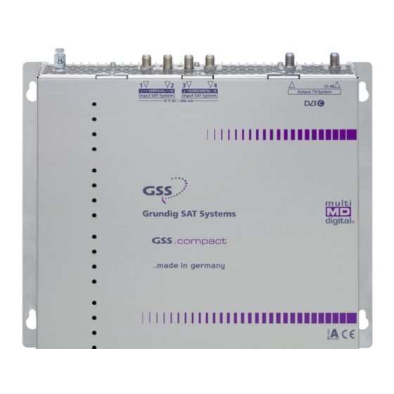
s s e m b l y 3.1 i n s ta l l i n g t h e d e v i C e – The device must not be operated lying down, since the function of the heat sink will be severely restricted. - Page 9 QAM output Test output –25dB IEC connector C14; connector for mains cable Reset IP address /host name / password (hold depressed for more than 5 seconds) to 192.168.0.120 / gss / geheim LAN socket** for configuration LAN-Status-LED Mounting support Without function...
-
Page 10: Potential Equalisation (Pe)
3.3 P (Pe) ot e n t i a l e q ua l i sat i o n Equalise the potential (PE) in accordance with IEC/EN/DIN EN 60728. • Connect the PE connection terminal to a PE rail (supplied by customer) using the PE wire (Cu 4 mm - 9 mm 3.4 C... -
Page 11: Configuration / Updates
/ u o n f i g u r a t i o n P d a t e s The configuration of the station is to be done via an HTML user interface via a PC and a standard HTML browser. 4.1 i n i t i a l C o n f i g u r at i o n... - Page 12 > Internet Protocol Version 4 (TCP/IPv4) > Properties • Activate point "Use the following IP address". • Enter e.g. 192.168.0.2 for the IP address. • Enter for the Subnet mask 255.255.255.0. • Confirm the setting with "OK". - 12 - STC 4-16 light...
- Page 13 • Start the browser, enter the IP address of the device (factory default is 192.168.0.120) and start the establishment of the connection. • Enter user "admin" and your Password and click on button "Login". The default password is "geheim". —> We recommend that you replace the default password to a pass- word of your choice in order to prevent unauthorized access to the head-end station (menu System >...
-
Page 14: Logbook
4.2 C o n f i g u r at i o n v e rv i e w w i n d ow Via the selection System you have access to the menus of the System settings: Logbook (page 23); Notification (page 24);... - Page 15 Via the Help menu you can call up the assembling instructions (PDF) as well as a ZIP file containing a list and all licences of the used Open- Source software. Overview of the transponder set, with input frequency, C/N value, output frequency and data rate.
- Page 16 o n f i g u r at i o n m e n u s n P u t —> Via the background colour of column Line you are informed about the quality of the input signals ( ), a possible exceeding the output data rate ( ), or whether the modulator is switched off In column f...
- Page 17 In column f , the current frequency offset is displayed. offset —> The frequency offset should not exceed ± 1.5 MHz! IF necessary correct the LNB oscillator frequency (if all transpond- ers of one input are affected) resp. the input frequency (if only one transponder is affected) accordingly.
- Page 18 u t P u t 155 156 —> Via the background colour of column Line you are informed about the quality of the input signals ( good/ bad/ no signal), a possible exceeding the output data rate ( ), or whether the modu- lator is switched off ( The upper value shows the current needed data rate.
- Page 19 In column Chan. / Freq. [MHz], enter the desired output channel/fre- quency of the individual lines. —> Double assignments are indicated by a warning icon —> A output signal is normally transmitted with a bandwidth of 8 MHz. This means that you can only use the channel centre frequency of the existing channel grid in the range of channels C21…C69 (frequency grid 8 MHz).
- Page 20 In column Level [dB], balance the output levels of the different lines (0…-10dB). Therefore measure and note down the output level of each modulator. Adjust the higher output levels to the output level of the modu- lator with the lowest output level incrementally. —>...
- Page 21 i lt e r In menu Filter you can remove stations/services (with adap- tation of the tables) and PIDs (Drop PIDs; without adaptation of the tables) from the data streams of the transponders. 207 208 —> For entering/indication of the different IDs the number format can be set to hexadecimal or decimal in menu System >...
- Page 22 —> If the filter is enabled, new services added to the transponder are suppressed until a hook is set. —> The background colour in column Line indicates an output data overflow. In this case check the values in column used/max/hold , change the output settings or remove stations from the data stream using the station filter.
- Page 23 ys t e m m e n u s o g b o o k In the logbook different alerts or events are displayed. This helps 300 301 302 at a possible troubleshooting. Herein you can select whether only one line is displayed or all lines are displayed.
- Page 24 ot i f i C at i o n In this menu you use the reaction time to set when entries for input signal or data overflow errors are entered in the logbook (page 23). Enter the access data for the outgoing mail server of your e-mail account here if you want to be informed about error entries in the logbook by e-mail.
- Page 25 Herein enter the mail address of the recipient. Via button send alarm mail you can send a test mail. —> Before you can send a test mail, changes must be transferred to the head-end station! Therefore click on button —> Example: —>...
- Page 26 IP address. To do this, enter the host name followed by ".local" in the browser (e.g. gss.local). If you operate several head stations in the network, you must enter different names here. —> Write down the IP address and the Host name! Further access to the device is only possible via the IP address or the host name.
- Page 27 e C u r i t y Herein replace the default password geheim by a password of your choice. —> We strongly recommend that you change the default password to prevent unauthorized access to the station. • For authorisation enter the "old" password and after that the "new" pass- word twice.
- Page 28 i r mwa r e Herein select the time zone, automatic daylight saving time and the number format (hexadecimal/decimal). In addition a firmware update, backup, fac- tory reset as well as a system restart (warm start) can be done. The manager allows you to store different configurations in the head-end station.
- Page 29 Herein you can select the number format for entering/indication the dif- ferent transport stream IDs (hexadecimal/decimal). Before leaving the menu, changes must be transferred to the head-end station! • Therefore click on button —> After that is displayed for a short time in the upper right corner. i r mwa r e u P dat e Herein the firmware version of the head-end station is displayed.
- Page 30 aC k u P Via button Save settings to PC you can download the settings from the head-end station as "*.tar" file for backup. —> Settings including password but without network settings. Via button Load settings from PC you can restore the settings from a prior downloaded backup.
- Page 31 i n g e t wo r k i ag n os t i C o o l You can use the Ping button to check whether a device is accessible on the network. • Enter the IP address you want to "ping" and click the Ping button. s e r In section User you can adjust the location-based data that is displayed in the header of the menus accordingly.
- Page 32 h a n n e l a n d f r e q u e n C y t a b l e s Advice for a frequency grid (8 MHz) in the Band I/III 42.00 82.00 146.00 186.00 226.00 266.00 50.00 114.00...
- Page 33 Declaration of CE conformity GSS Grundig Systems GmbH • Beuthener Straße 43 • D-90471 Nuremberg Phone: +49 (0) 911 / 633 240 0 • Fax: +49 (0) 911 / 633 240 98 www.gss.de/en • info@gss.de CLASS CLASS Service: Phone: +49 (0) 911/ 633 240 90 • service@gss.de Alterations reserved.
Need help?
Do you have a question about the compact classic STC 4-16 light and is the answer not in the manual?
Questions and answers