Advertisement
Quick Links
Specialists in fireplace design and manufacture
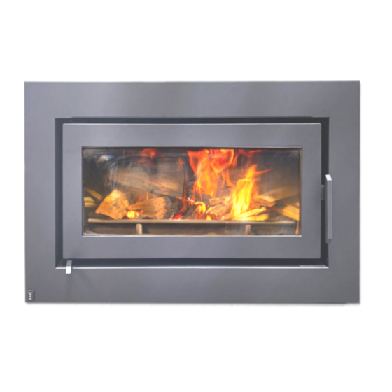
CELESTIAL 900 WITH FAN
INSTALLATION & OPERATING INSTRUCTIONS
IMPORTANT:
INSTALLER, PLEASE LEAVE THESE INSTRUCTIONS WITH THE UNIT ON COMPLETION.
10 YEAR FIREBOX WARRANTY
The firebox is covered by a 10 year warranty.
Other parts are covered by a one year limited warranty.
Head Office – 13 French Avenue, Brendale, Queensland 4500
Telephone – PH: (07) 3490 5500
Facsimile – FAX: (07) 3490 5520
Website: -
www.jetmaster.com.au
Business hours: - Monday to Thursday 7:30am-4:00pm. Friday 7:30am-2:00pm
Email: -
sales@jetmaster.com.au
20/08/2020
ver.5
1
Advertisement

Summary of Contents for Kemlan CELESTIAL 900 WITH FAN
- Page 1 Specialists in fireplace design and manufacture CELESTIAL 900 WITH FAN INSTALLATION & OPERATING INSTRUCTIONS IMPORTANT: INSTALLER, PLEASE LEAVE THESE INSTRUCTIONS WITH THE UNIT ON COMPLETION. 10 YEAR FIREBOX WARRANTY The firebox is covered by a 10 year warranty. Other parts are covered by a one year limited warranty.
- Page 2 DIMENSIONS CELESTIAL 900 WITH FAN AND HEAT DUCTING BOX FOR MASONRY / HEBEL FASCIA DESC. MODEL CELESTIAL 900 WALL INSERT 1054 1180 20/08/2020 ver.5...
- Page 3 HEARTH MEASUREMENT CELESTIAL 900 UNDERNEATH UNIT UNIT AND HEARTH THICKNESS MUST BE A MINIMUM 18mm NON COMBUSTIBLE MATERIAL FC SHEET OR SIMILAR UNIT HEIGHT ABOVE FLOOR HEARTH DIMENSION FORWARD OF UNIT 20/08/2020 ver.5...
- Page 4 HEARTH REQUIREMENTS FOR INSTALLATION ONTO A RAISED HEARTH UNDERNEATH UNIT AND HEARTH THICKNESS MUST BE CELESTIAL 900 A MINIMUM 18mm UNIT NON COMBUSTIBLE MATERIAL FC SHEET OR SIMILAR MIN. DEPTH MEASUREMENT (mm) MIN. HEIGHT INCREASE (mm) 200* * NOTE: IF Y IS LESS THAN 200mm THEN REFER TO HEARTH MEASUREMENT ON PREVIOUS PAGE 20/08/2020 ver.5...
- Page 5 BAFFLE PLATE INSTALLATION 1. REMOVE MIDDLE AIR TUBE BY PUSHING 2. PLACE ALL 4 BAFFLE PLATES ABOVE AIR TUBES UP AND REMOVING FROM FRONT AND BOTH SIDES CLOSEST TO THE FIRE BOX WALL REAR BRACKETS. AS SHOWN ( 2 LEFT AND 2 RIGHT) 3.
- Page 6 CELESTIAL 900 MASONRY BLOCK CONSTRUCTION Flue system to be installed to suit AS/NZS 2918.2001 plain crimped Triple skin flue system All 8”-10” assembled flues must (10”, 8” and 6”) have the crimps pointing upwards DETAIL A 25mm min. clearance between 10”...
- Page 7 CELESTIAL 900 MASONRY BLOCK CONSTRUCTION 25mm min. clearance between 10” flue and ceiling/framing Flue system to be installed to suit AS/NZS 2918.2001 Triple skin flue system (10”, 8” and 6”) 9mm Fibre cement 600mm min. sheet Below ceiling Register plate with vented 8”...
- Page 8 CELESTIAL 900 MASONRY OPENING CUT SIZE 1165 NOTE: THE APPLIANCE WILL NEED 505mm DEEP OPENING TO THE BACK OF CHASE 20/08/2020 ver.5...
- Page 9 PYROTEK ZERO CLEARANCE INSTALLATION 15mm CLEARANCE COMBUSTIBLE TOP VIEW MATERIAL 25mm PYROTEK BOARD ASSEMBLY 15mm CLEARANCE BETWEEN PYROTEK AND COMBUSTIBLE MATERIAL 25mm CLEARANCE FROM OUTER FLUE TO COMBUSTIBLE FRONT VIEW MATERIAL CEILING STEEL TRACK NOTE: FRONT FACE ONLY NEEDS TO BE NON COMBUSTIBLE TO CEILING.
- Page 10 DIMENSIONS FOR WHITE BOARD ZERO CLEARANCE BOX CELESTIAL 900 WITH FAN 1254 1073 20/08/2020 ver.5...
- Page 11 CELESTIAL 900 FASCIA INSTALLATION INFORMATION 1.OPEN THE DOOR TO ABOUT 70 DEGREES 2. THREAD ONE SCREW AND ONE WASHER TO THE FRONT OF THE FIREBOX. LIFT (SUPPLIED) TO EVERY NUT SERT SHOWN. MAKE THE DOOR UPWARDS UNTIL THE DOOR SURE THE WASHER IS AS CLOSE TO THE SCREW CLEARS THE HINGES AND MOVE IT OUT OF HEAD AS POSSIBLE.
- Page 12 CELESTIAL 900 WITH FAN DOOR ADJUSTMENT INFORMATION MARK THE POSITION OF THE ADJUSTMENT OPEN THE DOOR AS FAR AS REQUIRED, AND ANGLE ON THE FIREBOX. IT IS CRITICAL TO THE ADJUSTMENT ANGLE IS ACCESSIBLE. PUT THE ADJUSTMENT ANGLE AT THE SAME SPOT.
- Page 13 CELESTIAL 900 WITH FAN REMOVAL / INSTALLATION CONNECTORS TO FAN WIRES EARTH WIRE CONNECTORS TO FASCIA REMOVE 2 SCREWS HOLDING THE FAN UNPLUG THE FAN CONNECTOR FROM THE CASSETTE IN PLACE FASCIA CONNECTOR, UNSCREW THE EARTH WIRE FROM THE APPLIANCE . REMOVE THE...
-
Page 14: Installation Instructions
INSTALLATION INSTRUCTIONS MINIMUM HEIGHT OF FLUE SYSTEM EXIT INSTALLATION TO COMPLY WITH AS/NZS 2918 ANY NEARBY STRUCTURE 3000 3000 OR LESS MORE THAN 3000 600 MIN 3000 INCREASE AS NECESSARY UNTIL NOTHING WITHIN 3000 OF FLUE TOP 1000 MIN IF CLEAR WITHIN 3000 OF TOP OF FLUE 3000 OR LESS 3000... - Page 15 20/08/2020 ver.5...
- Page 16 INSTRUCTIONS FOR OPERATING YOUR KEMLAN SLOW COMBUSTION WOOD BURNING HEATER Open the air inlet fully by sliding the air inlet control to high. Crumple at least three double pages of newspaper into loose balls and place them into the centre of the firebox.
- Page 17 ver.5 20/08/2020...
-
Page 18: Operating Hints
The same will apply with fuel which is not fully seasoned or is not dry enough. Kemlan have followed a policy since 1969 of checking on all complaints about poor performance of their heaters and apart from a few instances of incorrect installation (mostly insufficient flue length) all problems have been directly related to incorrect operation and/or poor fuel. -
Page 19: This Warranty Does Not Cover
4.9 Cost of inspection for damaged heater. CLAIMS – 5.1 (I) Kemlan will provide a full replacement of the heater in the first five years after installation. (ii) Replacement in the subsequent five years (i.e. sixth to tenth year after installation will be on the following basis. - Page 20 NOTES 20/08/2020 ver.5...
- Page 21 20/08/2020 ver.5...
- Page 22 20/08/2020 ver.5...
Need help?
Do you have a question about the CELESTIAL 900 WITH FAN and is the answer not in the manual?
Questions and answers