Table of Contents
Advertisement
Quick Links
Quick Start
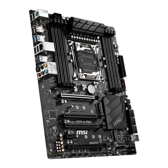
Thank you for purchasing the MSI®
X299-A PRO
motherboard. This Quick Start section
provides demonstration diagrams about how to install your computer. Some of the
installations also provide video demonstrations. Please link to the URL to watch it
with the web browser on your phone or tablet. You may have even link to the URL by
scanning the QR code.
Preparing Tools and Components
Intel® LGA 2066 CPU
CPU Fan
Chassis
DDR4 Memory
Power Supply Unit
Graphics Card
Thermal Paste
SATA Hard Disk Drive
SATA DVD Drive
A Package of Screws
Phillips Screwdriver
1
Quick Start
Advertisement
Table of Contents

Related Manuals for MSI X299-A PRO


Summary of Contents for MSI X299-A PRO
-
Page 1: Quick Start
Quick Start Thank you for purchasing the MSI® X299-A PRO motherboard. This Quick Start section provides demonstration diagrams about how to install your computer. Some of the installations also provide video demonstrations. Please link to the URL to watch it with the web browser on your phone or tablet. -
Page 2: Safety Information
Safety Information ∙ The components included in this package are prone to damage from electrostatic discharge (ESD). Please adhere to the following instructions to ensure successful computer assembly. ∙ Ensure that all components are securely connected. Loose connections may cause the computer to not recognize a component or fail to start. -
Page 3: Installing A Processor
Installing a Processor ⚽ https://youtu.be/ecdkLMmkya4 Safety Information... -
Page 4: Installing Ddr4 Memory
Installing DDR4 memory ⚽ http://youtu.be/T03aDrJPyQs Safety Information... -
Page 5: Connecting The Front Panel Header
Connecting the Front Panel Header ⚽ http://youtu.be/DPELIdVNZUI Power LED Power Switch JFP1 Reserved HDD LED Reset Switch HDD LED + Power LED + HDD LED - Power LED - Reset Switch Power Switch JFP1 Reset Switch Power Switch Reserved No Pin HDD LED - HDD LED HDD LED +... -
Page 6: Installing The Motherboard
Installing the Motherboard ⚽ https://youtu.be/wWI6Qt51Wnc Torque: 3 kgf·cm* *3 kgf·cm = 0.3 N·m = 2.6 lbf·in Safety Information... -
Page 7: Connecting The Power Connectors
Connecting the Power Connectors ⚽ http://youtu.be/gkDYyR_83I4 CPU_PWR1 ATX_PWR1 Safety Information... -
Page 8: Installing Sata Drives
Installing SATA Drives http://youtu.be/RZsMpqxythc Safety Information... -
Page 9: Installing A Graphics Card
Installing a Graphics Card http://youtu.be/mG0GZpr9w_A Safety Information... -
Page 10: Connecting Peripheral Devices
Connecting Peripheral Devices Safety Information... -
Page 11: Power On
Power On Safety Information... -
Page 12: Table Of Contents
Contents Quick Start ......................1 Preparing Tools and Components................1 Safety Information ....................2 Installing a Processor .................... 3 Installing DDR4 memory ..................4 Connecting the Front Panel Header ..............5 Installing the Motherboard ..................6 Connecting the Power Connectors ................ 7 Installing SATA Drives .................... - Page 13 JBAT1: Clear CMOS (Reset BIOS) Jumper ............41 JCI1: Chassis Intrusion Connector ............... 42 JRGB1: RGB LED connector ................. 43 Onboard LEDs ...................... 44 EZ Debug LED ....................... 44 XMP LED ....................... 44 Installing OS, Drivers & Utilities ................. 45 Installing Windows®...
-
Page 14: Specifications
∙ Supports Intel® Extreme Memory Profile (XMP) ∙ Supports non-ECC UDIMM memory ∙ Supports un-buffered memory * For the latest information about memory, please visit http://www.msi.com ** Please refer the DIMM Slots section for more details. ∙ 4x PCIe 3.0 x16 slots ▪... - Page 15 Continued from previous page Intel® X299 Chipset ∙ Supports RAID 0, RAID1, RAID 5 and RAID 10 for SATA RAID storage devices ∙ Supports RAID 0 and RAID 1 for M.2 PCIe storage devices 1x Intel I219-V Gigabit LAN controller* * I219 LAN doesn’t support G3 to S5 Wake ∙...
- Page 16 Continued from previous page ∙ 1x 24-pin ATX main power connector ∙ 1x 8-pin ATX 12V power connector ∙ 8x SATA 6Gb/s connectors ∙ 2x USB 2.0 connectors (supports additional 4 USB 2.0 ports) ∙ 2x USB 3.2 Gen1 connectors (supports additional 4 USB 3.2 Gen1 ports) ∙...
- Page 17 Continued from previous page ∙ Drivers ∙ DRAGON CENTER Software ∙ CPU-Z MSI GAMING ∙ Google Chrome™, Google Toolbar, Google Drive ∙ Norton™ Internet Security Solution ∙ Mystic Light ∙ Hardware Monitor ∙ True Color ∙ Live Update Dragon Center Features ∙...
- Page 18 Continued from previous page ∙ Protection ▪ PCI-E Steel Armor ▪ U.2 Steel Armor ∙ Performance ▪ Multi GPU – SLI Technology ▪ Multi GPU – CrossFire Technology ▪ DDR4 Boost ▪ OC Engine(Clock gen) ▪ USB with type A+C ▪...
-
Page 19: Package Contents
Package contents Please check the contents of your motherboard package. It should contain: Motherboard X299-APRO User manual Documentation Case stand-off notification Quick installation guide Application Driver DVD Cables SATA 6G cables Case badge SATA cable stickers Accessories Product registration card IO shielding M.2 screws ⚠... -
Page 20: Block Diagram
Block Diagram 4 Channel DDR4 Memory Processor PCI Express Bus DMI 3.0 1x U.2 Switch PCIe x1 slot 2x M.2 Switch 8x SATA 6Gb/s ASMEDIA X299 PCH ASM3142 3x USB 3.2 Gen2 PCIE Bus 8x USB 3.2 Gen1 Intel I219-V Gigabit LAN 5x USB 2.0 GL850... -
Page 21: Rear I/O Panel
Rear I/O Panel Audio Ports PS/2 Optical S/PDIF-Out USB 2.0 USB 2.0 USB 3.2 Gen2 Type-C USB 3.2 Gen1 Clear CMOS Button USB 3.2 Gen2 Type-A ∙ Clear CMOS button - Power off your computer. Press and hold the Clear CMOS button for about 5-10 seconds to reset BIOS to default values. -
Page 22: Realtek Audio Console
Realtek Audio Console After Realtek Audio Console is installed. You can use it to change sound settings to get better sound experience. Application Enhancement Device Selection Main Volume Connector Settings Jack Status ∙ Device Selection - allows you to select a audio output source to change the related options. - Page 23 Audio jacks to headphone and microphone diagram Audio jacks to stereo speakers diagram AUDIO INPUT Audio jacks to 7.1-channel speakers diagram AUDIO INPUT Rear Front Side Center/ Subwoofer Rear I/O Panel...
-
Page 24: Overview Of Components
Overview of Components PUMP_FAN1 CPU_PWR1 CPU_FAN1 SYS_FAN1 CPU Socket DIMMA2 DIMMD1 DIMMA1 DIMMD2 DIMMC1 DIMMB2 DIMMC2 DIMMB1 ATX_PWR1 JUSB4 JUSB5 PCI_E1 JUSB3 M2_1 SATA▼1▲2 PCI_E2 SATA▼3▲4 PCI_E3 SATA▼5▲6 M2_2 PCI_E4 U2_1 BIOS_SW1 PCI_E5 SATA7 SATA8 VRAID1 JRGB1 SYS_FAN4 JFP2 JUSB1 SYS_FAN3 SYS_FAN2 JTBT1... - Page 25 Component Contents Port Name Port Type Page BIOS_SW1 Multi-BIOS Switch CPU_FAN1, PUMP_FAN1, Fan Connectors SYS_FAN1~4 CPU_PWR1, ATX_PWR1 Power Connectors CPU Socket LGA2066 CPU Socket DIMM Slots Memory slots JAUD1 Front Audio Connector JBAT1 Clear CMOS (Reset BIOS) Jumper JCI1 Chassis Intrusion Connector JFP1, JFP2 Front Panel Connectors JRGB1...
-
Page 26: Cpu Socket
∙ the CPU. ∙ Please retain the CPU protective cap after installing the processor. MSI will deal with Return Merchandise Authorization (RMA) requests if only the motherboard comes with the protective cap on the CPU socket. When installing a CPU, always remember to install a CPU heatsink. A CPU heatsink ∙... -
Page 27: Dimm Slots
DIMM Slots S/K LED : S/K LED indicates that the installed CPU supports either 4-channels or 2-channels memory architecture. Red = 8 DIMMs support (4-channels architecture CPU) White = 4 DIMMs support (2-channels architecture CPU) B1B2A1A2 C2C1D2D1 Memory module installation recommendation Intel Core X-series CPU 1 DIMM 2 DIMMs... - Page 28 It is recommended to use a more efficient memory cooling system for full DIMMs installation or overclocking. The stability and compatibility of installed memory module depend on installed CPU ∙ and devices when overclocking. Please refer www.msi.com for more information on compatible memory. ∙ Overview of Components...
- Page 29 Memory module installation recommendation (2-Channels architecture CPU ) Intel Core X-series CPU 1 DIMM 2 DIMMs Supports 2-channels memory architecture 3 DIMMs 4 DIMMs DIMMB1, B2, A1 and A2 are un-available DIMMC1 DIMMC1 DIMMD1 DIMMC2 DIMMC2 DIMMC1 DIMMC1 DIMMD2 DIMMD1 DIMMD1 Overview of Components...
-
Page 30: Pci_E1~5: Pcie Expansion Slots
PCI_E1~5: PCIe Expansion Slots Please refer to the table below for the PCIe lanes of the CPU. 48-lane CPU 44-lane CPU 28-lane CPU 16-lane CPU PCI_E1 PCIe x16 PCIe x16 PCIe x16 PCIe x8 PCIe x8 PCI_E2 PCIe x4 PCIe x4 PCIe x4 PCIe x4 PCIe x4... - Page 31 ⚠ Important ∙ If you install a large and heavy graphics card, you need to use a tool such as MSI Gaming Series Graphics Card Bolster to support its weight to prevent deformation of the slot. For a single PCIe x16 expansion card installation with optimum performance, using ∙...
-
Page 32: Cpu_Pwr1, Atx_Pwr1: Power Connectors
CPU_PWR1, ATX_PWR1: Power Connectors These connectors allow you to connect an ATX power supply. CPU_PWR1 Ground +12V Ground +12V Ground +12V Ground +12V +3.3V +3.3V +3.3V -12V Ground Ground PS-ON# Ground Ground Ground ATX_PWR1 Ground Ground PWR OK 5VSB +12V +12V +3.3V Ground... -
Page 33: Jfp1, Jfp2: Front Panel Connectors
JFP1, JFP2: Front Panel Connectors These connectors connect to the switches and LEDs on the front panel. Power LED Power Switch JFP1 Reserved HDD LED Reset Switch HDD LED + Power LED + HDD LED - Power LED - Reset Switch Power Switch Reset Switch Power Switch... -
Page 34: U2_1: U.2 Connector
U2_1: U.2 Connector This connector is a U.2 interface port. Each connector can connect to one PCIe 3.0 x4 NVMe storage device. ⚽ Video Demonstration Watch the video to learn how to Install U.2 SSD. http://youtu.be/KgFvKDxymvw Installing U.2 SSD 1. Connect the U.2 cable to the U.2 connector on the motherboard. -
Page 35: Sata1~8: Sata 6Gb/S Connectors
SATA1~8: SATA 6Gb/s Connectors These connectors are SATA 6Gb/s interface ports. Each connector can connect to one SATA device. SATA2 SATA1 SATA4 SATA3 SATA6 SATA5 SATA7 ⚠ SATA8 Important Please do not fold the SATA cable at a 90-degree angle. Data loss may result during ∙... -
Page 36: Vraid1: Virtual Raid On Cpu Connector
M.2 slots with examples of various combination possibilities 1xM.2 PCIe SSD + 8xSATA HDDs + 1xM.2 PCIe SSD + 1xM.2 SATA SSD 1xU.2 SSD +7xSATA HDDs + 1xU.2 SSD M.2 PCIe M.2 PCIe M.2 SATA SATA7 SATA7 SATA8 SATA8 2xM.2 PCIe SSDs + 4xSATA HDDs + 2xM.2 SATA SSDs + 6xSATA HDDs + 1xU.2 SSD 1xPCI_E3 device... -
Page 37: Jaud1: Front Audio Connector
JAUD1: Front Audio Connector This connector allows you to connect audio jacks on the front panel. MIC L Ground MIC R Head Phone R MIC Detection SENSE_SEND No Pin Head Phone L Head Phone Detection CPU_FAN1, PUMP_FAN1, SYS_FAN1~4: Fan Connectors Fan connectors can be classified as PWM (Pulse Width Modulation) Mode or DC Mode. -
Page 38: Jusb1~2: Usb 2.0 Connectors
∙ damage. ∙ In order to recharge your iPad,iPhone and iPod through USB ports, please install MSI DRAGON CENTER utility. JUSB3~4: USB 3.2 Gen1 Connectors These connectors allow you to connect USB 3.2 Gen1 ports on the front panel. Power USB2.0+... -
Page 39: Jusb5: Usb 3.2 Gen2 Type-C Connector
JUSB5: USB 3.2 Gen2 Type-C Connector This connector allows you to connect USB 3.2 Gen2 Type-C connector on the front panel. The connector possesses a foolproof design. When you connect the cable, be sure to connect it with the corresponding orientation. USB Type-C port on the front panel USB Type-C Cable... -
Page 40: Bios_Sw1: Multi-Bios Switch
When BIOS updating fails or causes the computer non-bootable, you can recover the failed BIOS by the steps below. Before recovering, please download the latest BIOS file that matches your motherboard model from MSI website. And then save the BIOS file to the root of the USB flash drive. -
Page 41: Power1, Reset1: Power Button, Reset Button
POWER1, RESET1: Power Button, Reset Button The Power / Reset button allows you to power on / reset the computer. Power button Reset button JBAT1: Clear CMOS (Reset BIOS) Jumper There is CMOS memory onboard that is external powered from a battery located on the motherboard to save system configuration data. -
Page 42: Jci1: Chassis Intrusion Connector
JCI1: Chassis Intrusion Connector This connector allows you to connect the chassis intrusion switch cable. Normal Trigger the chassis intrusion event (default) Using chassis intrusion detector 1. Connect the JCI1 connector to the chassis intrusion switch/ sensor on the chassis. 2. -
Page 43: Jrgb1: Rgb Led Connector
(12V/G/R/B) with the maximum power rating of 3A (12V). ∙ Always turn off the power supply and unplug the power cord from the power outlet before installing or removing the RGB LED strip. Please use MSI’s software to control the extended LED strip. ∙ Overview of Components... -
Page 44: Onboard Leds
Onboard LEDs EZ Debug LED These LEDs indicate the debug status of the motherboard. CPU - indicates CPU is not detected or fail. DRAM - indicates DRAM is not detected or fail. VGA - indicates GPU is not detected or fail. BOOT - indicates the booting device is not detected or fail. -
Page 45: Installing Os, Drivers & Utilities
Installing OS, Drivers & Utilities Please download and update the latest utilities and drivers at www.msi.com Installing Windows® 10 1. Power on the computer. 2. Insert the Windows® 10 installation disc/USB into your computer. 3. Press the Restart button on the computer case. -
Page 46: Bios Setup
∙ Press Delete key, when the Press DEL key to enter Setup Menu, F11 to enter Boot Menu message appears on the screen during the boot process. ∙ In MSI Dragon Center application, click on GO2BIOS button and choose OK. The system will reboot and enter BIOS setup directly. -
Page 47: Resetting Bios
Updating BIOS Updating BIOS with M-FLASH Before updating: Please download the latest BIOS file that matches your motherboard model from MSI website. And then save the BIOS file into the USB flash drive. Updating BIOS: 1. Insert the USB flash drive that contains the update file into the USB port. -
Page 48: Ez Mode
EZ Mode At EZ mode, it provides the basic system information and allows you to configure the basic setting. To configure the advanced BIOS settings, please enter the Advanced Mode by pressing the Setup Mode switch or F7 function key. XMP switch Setup Mode switch Screenshot... - Page 49 ∙ Information display - click on the CPU, Memory, Storage, Fan Info and Help buttons on left side to display related information. ∙ Function buttons - enable or disable the LAN Option ROM, M.2/Optane Genie, Hardcore Mode, AHCI/RAID, Indication LED Control and RGB Light Control by clicking on their respective button.
-
Page 50: Advanced Mode
Advanced Mode Press Setup Mode switch or F7 function key can switch between EZ Mode and Advanced Mode in BIOS setup. XMP switch Setup Mode switch Screenshot Language System information OC GENIE 4 switch Boot device priority bar BIOS menu BIOS menu selection selection... -
Page 51: Settings
SETTINGS System Status ▶ System Date Sets the system date. Use tab key to switch between date elements. The format is <day> <month> <date> <year>. <day> Day of the week, from Sun to Sat, determined by BIOS. Read-only. <month> The month from Jan. through Dec. <date>... - Page 52 ▶ PEG X - Max Link Speed [Auto] Sets PCI Express protocol of PCIe x16 slots for matching different installed devices. [Auto] This item will be configured automatically by BIOS. [Gen1] Enables PCIe Gen1 support only. [Gen2] Enables PCIe Gen2 support only. [Gen3] Enables PCIe Gen3 support only.
- Page 53 ▶ Network Stack [Disabled] Sets UEFI network stack for optimizing IPv4 / IPv6 function. [Enabled] Enables UEFI network stack. [Disabled] Disables UEFI network stack. ▶ Ipv4 PXE Support [Enabled] When Enabled, the system UEFI network stack will support Ipv4 protocol. This item will appear when Network Stack is enabled.
- Page 54 ▶ XHCI Hand-off [Diasbled] Enables or disables XHCI hand-off support for the operating system without XHCI hand-off feature. ▶ Legacy USB Support [Enabled] Sets Legacy USB function support. [Auto] The system will automatically detect if any USB device is connected and enable the legacy USB support.
- Page 55 ▶ MSI Fast Boot [Disabled] MSI Fast Boot is the fastest way to boot the system. It will disable more devices to speed up system boot time which is faster than the boot time of Fast Boot. [Enabled] Enables the MSI Fast Boot function to speed up booting time. And the following Fast Boot field will be disabled and fixed.
- Page 56 ▶ Resume By RTC Alarm [Disabled] Disables or enables the system wake up by RTC Alarm. [Enabled] Enables the system to boot up on a scheduled time/ date. [Disabled] Disables this function. ▶ Date (of month) Alarm/ Time (hh:mm:ss) Alarm Sets RTC alarm date/ Time.
-
Page 57: Boot
Boot Sets the sequence of system boot devices. ▶ Full Screen Logo Display [Enabled] Enables or disables to show the full screen logo while system POST. [Enabled] Shows the logo in full screen. [Disabled] Shows the POST messages. ▶ GO2BIOS [Disabled] Allows system to enter BIOS setup directly by pressing the Power button for 4 sec pon bootup. -
Page 58: Security
Security ▶ Administrator Password Sets administrator password for system security. User has full rights to change the BIOS items with administrator password. After setting the administrator password, the state of this item will show “Installed”. ▶ User Password Sets User Password for system security. User has limited rights to change the BIOS items with user password. -
Page 59: Save & Exit
Save & Exit ▶ Discard Changes and Exit Exit BIOS setup without saving any change. ▶ Save Changes and Reboot Save all changes and reboot the system. ▶ Save Changes Save current changes. ▶ Discard Changes Discard all changes and restore to the previous values. ▶... - Page 60 ⚠ Important Overclocking your PC manually is only recommended for advanced users. ∙ Overclocking is not guaranteed, and if done improperly, it could void your warranty ∙ or severely damage your hardware. ∙ If you are unfamiliar with overclocking, we advise you to use OC GENIE 4 function for easy overclocking.
- Page 61 ▶ Core X X of X xxxx MHz [Auto]* Allows you to set the CPU ratios for different number of active cores. These items only appear when CPU Ratio Apply Mode set to Per Core. ▶ CPU Ratio Offset When Running AVX [Auto] Sets a offset value to lower the CPU core ratio.
- Page 62 ▶ Extreme Memory Profile (X.M.P.) [Disabled] X.M.P. (Extreme Memory Profile) is the overclocking technology by memory module. Please enable XMP or select a profile of memory module for overclocking the memory. This item will be available when the memory modules that support X.M.P. is installed.
- Page 63 ▶ DRAM Voltages control [Auto] These options allows you to set the voltages related to memory. If set to Auto, BIOS will set these voltages automatically or you can set it manually. ▶ CPU Memory Changed Detect [Enabled]* Enables or disables the system to issue a warning message during boot when the CPU or memory has been replaced.
- Page 64 ▶ Limit CPUID Maximum [Disabled] Enables or disables the extended CPUID value. [Enabled] BIOS limits the maximum CPUID input value to circumvent boot problems with older operating system that do not support the processor with extended CPUID value. [Disabled] Use the actual maximum CPUID input value. ▶...
- Page 65 ▶ C1E Support [Disabled] Enables or disables the C1E function for power-saving in halt state. This item appears when Intel C-State is enabled. [Enabled] Enables C1E function to reduce the CPU frequency and voltage for power-saving in halt state. [Disabled] Disables this function.
-
Page 66: M-Flash
M-FLASH provides the way to update BIOS with a USB flash drive. Please down-load the latest BIOS file that matches your motherboard model from MSI website, save the BIOS file into your USB flash drive. And then follow the steps below to update BIOS. -
Page 67: Oc Profile
OC PROFILE ▶ Overclocking Profile 1/ 2/ 3/ 4/ 5/ 6 Overclocking Profile 1/ 2/ 3/ 4/ 5/ 6 management. Press <Enter> to enter the sub- menu. ▶ Set Name for Overclocking Profile 1/ 2/ 3/ 4/ 5/ 6 Name the current overclocking profile. ▶... -
Page 68: Hardware Monitor
HARDWARE MONITOR Temperature & Speed Fan Manage Setting Buttons Temperature/ Voltage display ▶ Temperature & Speed Shows the current CPU temperature, system temperature and fans' speeds. ▶ Fan Manage ▪ PWM - allows you to select the PWM mode for fan operation. ▪... -
Page 69: Raid Configuration
RAID Configuration Below are the different types of a RAID. RAID 0 breaks the data into blocks which are written to separate hard drives. Spreading the hard drive I/O load across independent channels greatly improves I/O performance. RAID 1 provides data redundancy by mirroring data between the hard drives and provides enhanced read performance. -
Page 70: Creating Raid Volume
Press F10 to save configuration and exit, and then reboot and press Delete key to enter BIOS Setup menu. Go to BIOS > SETTING > Advanced > Intel(R) Rapid Storage Technology sub- menu. Creating RAID Volume As previously mentioned, enable Intel(R) Rapid Storage Technology. Enter Create RAID Volume screen. -
Page 71: Removing A Raid Volume
Removing a RAID Volume Here you can delete the RAID volume, but please be noted that all data on RAID drives will be lost. ⚠ Important If your system currently boots to RAID and you delete the RAID volume, your system will become unbootable. -
Page 72: Resetting Disks To Non-Raid
Resetting Disks to Non-RAID Go to BIOS > SETTING > Advanced > Intel(R) Rapid Storage Technology. Select the RAID volume from the Intel(R) Rapid Storage Technology screen to enter the RAID VOLUME INFO screen. Select the disk and press Enter to enter PHYSICAL DISK INFO screen. Select Reset to non-RAID item and press Enter to delete the RAID volume and remove any RAID structures from the drives. -
Page 73: Rebuilding Raid Array
Rebuilding RAID Array A RAID 1, RAID 5 or RAID 10 volume is reported as Degraded when one of its hard drive members fails or is temporarily disconnected, and data mirroring is lost. As a result, the system can only utilize the remaining functional hard drive member. To re- establish data mirroring and restore data redundancy, refer to the procedure below that corresponds to the current situation. -
Page 74: Installing Raid Driver
When prompted, insert the USB flash drive with Intel RAID Drivers and then click Browse. ▪ To make an Intel RAID Drivers USB flash drive. Insert the MSI Driver Disc into the optical drive. Copy the RAID driver in \\Storage\Intel\ Navigate to the directory containing the saved Intel RAID drivers, then click OK. -
Page 75: Intel® Optane™ Memory Configuration
▪ Reboot to operating system. ▪ Insert the MSI Driver Disc into the optical drive. ▪ Click the Select to choose what happens with this disc pop-up notification, then select Run DVDSetup.exe to open the installer. If you turn off the AutoPlay feature from the Windows Control Panel, you can still manually execute the DVDSetup.exe... - Page 76 Enable Intel® Optane™ Memory. ▪ Run the Intel® Rapid Storage Technology software. ▪ Click Intel® Optane™ Memory tab and click Enable. ▪ Click Yes in the dialog. Reboot System. ⚠ WARNING Once you enable Intel® Optane™ memory, in order to prevent seriously damage your operating system, please follow the cautions listed below.
-
Page 77: Removing The Intel® Optane™ Memory
Removing the Intel® Optane™ memory If you no longer want to use Intel® Optane™ memory, you have to disable the Intel® Optane™ memory before removing the Intel® Optane™ memory module to avoid operating system damage. Please follow the steps below to remove the Intel® Optane™... -
Page 78: Troubleshooting
Troubleshooting Lost BIOS password Before sending the motherboard for RMA repair, try to go over troubleshooting ∙ Clear the CMOS, but that will cause guide first to see if your got similar you to lose all customized settings in the symptoms as mentioned below. - Page 79 European Harmonized Standards. disposing of their end-of-life products. The point of contact for regulatory matters is MSI, • Visit the MSI website and locate a nearby distributor MSI-NL Eindhoven 5706 5692 ER Son. for further recycling information. B급 기기 (가정용 방송통신기자재) •...
- Page 80 MSI la Unión Europea al final de su periodo de vida. Usted will comply with the product take back requirements...
- Page 81 Products designed to be operated del suo ciclo di vita. MSI si adeguerà a tale Direttiva at closer proximities, such as tablet computers, ritirando tutti i prodotti marchiati MSI che sono stati comply with applicable EU requirements in typical venduti all’interno dell’Unione Europea alla fine del...
- Page 82 Copyright © 2019 All rights reserved. contact your place of purchase or local distributor. The MSI logo used is a registered trademark of Alternatively, please try the following help resources Micro-Star Int’l Co., Ltd. All other marks and names for further guidance.
Need help?
Do you have a question about the X299-A PRO and is the answer not in the manual?
Questions and answers