Table of Contents
Advertisement
Available languages
Available languages
Quick Links
Quick Start
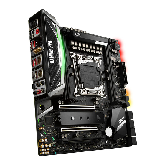
Thank you for purchasing the MSI
X299M GAMING PRO CARBON
®
AC
motherboard. This Quick Start section provides demonstration
diagrams about how to install your computer. Some of the
installations also provide video demonstrations. Please link to the
URL to watch it with the web browser on your phone or tablet. You
may have even link to the URL by scanning the QR code.
Kurzanleitung
Danke, dass Sie das MSI
X299M GAMING PRO CARBON AC
®
Motherboard gewählt haben. Dieser Abschnitt der Kurzanleitung
bietet eine Demo zur Installation Ihres Computers. Manche
Installationen bieten auch die Videodemonstrationen. Klicken Sie
auf die URL, um diese Videoanleitung mit Ihrem Browser auf Ihrem
Handy oder Table anzusehen. Oder scannen Sie auch den QR Code
mit Ihrem Handy, um die URL zu öffnen.
Présentation rapide
Merci d' avoir choisi la carte mère MSI
X299M GAMING PRO
®
CARBON
AC. Ce manuel fournit une rapide présentation avec
des illustrations explicatives qui vous aideront à assembler votre
ordinateur. Des tutoriels vidéo sont disponibles pour certaines
étapes. Cliquez sur le lien fourni pour regarder la vidéo sur votre
téléphone ou votre tablette. Vous pouvez également accéder au lien
en scannant le QR code qui lui est associé.
Быстрый старт
Благодарим вас за покупку материнской платы MSI
X299M
®
AC. В этом разделе представлена
GAMING PRO CARBON
информация, которая поможет вам при сборке комьютера.
Для некоторых этапов сборки имеются видеоинструкции.
Для просмотра видео, необходимо открыть
соответствующую ссылку в веб-браузере на вашем телефоне
или планшете. Вы также можете выполнить переход по
ссылке, путем сканирования QR-кода.
I
Quick Start
Advertisement
Chapters
Table of Contents

Related Manuals for MSI X299M GAMING PRO CARBON AC


Summary of Contents for MSI X299M GAMING PRO CARBON AC
- Page 1 URL, um diese Videoanleitung mit Ihrem Browser auf Ihrem Handy oder Table anzusehen. Oder scannen Sie auch den QR Code mit Ihrem Handy, um die URL zu öffnen. Présentation rapide Merci d’ avoir choisi la carte mère MSI X299M GAMING PRO ® CARBON AC.
- Page 2 Installing a Processor/ Installation des Prozessors/ Installer un processeur/ Установка процессора https://youtu.be/ecdkLMmkya4 Quick Start...
- Page 3 Installing DDR4 memory/ Installation des DDR4-Speichers/ Installer une mémoire DDR4/ Установка памяти DDR4 http://youtu.be/T03aDrJPyQs Quick Start...
- Page 4 Connecting the Front Panel Header/ Anschließen der Frontpanel-Stiftleiste/ Connecter un connecteur du panneau avant/ Подключение разъемов передней панели http://youtu.be/DPELIdVNZUI HDD LED + Power LED + HDD LED - Power LED - Reset Switch Power Switch Reset Switch Power Switch JFP1 Reserved No Pin JFP1...
- Page 5 Installing the Motherboard/ Installation des Motherboards/ Installer la carte mère/ Установка материнской платы BAT1 Quick Start...
- Page 6 Installing SATA Drives/ Installation der SATA-Laufwerke/ Installer le disque dur SATA/ Установка дисков SATA http://youtu.be/RZsMpqxythc Quick Start...
- Page 7 Installing a Graphics Card/ Einbau der Grafikkarte/ Installer une carte graphique/ Установка дискретной видеокарты http://youtu.be/mG0GZpr9w_A Quick Start...
- Page 8 Connecting Peripheral Devices/ Peripheriegeräte/ Connecter un périphérique anschliessen/ Подключение периферийных устройств VIII Quick Start...
- Page 9 Connecting the Power Connectors/ Stromanschlüsse anschliessen/ Connecter les câbles du module d’ alimentation/ Подключение разъемов питания http://youtu.be/gkDYyR_83I4 ATX_PWR1 CPU_PWR1 PCIE_PWR1 Quick Start...
- Page 10 Power On/ Einschalten/ Mettre sous-tension/ Включение питания Quick Start...
-
Page 11: Table Of Contents
Contents Safety Information ....................3 Specifications ......................4 Rear I/O Panel ..................... 10 LAN Port LED Status Table................... 10 Audio Ports Configuration ..................10 Realtek HD Audio Manager .................. 11 Overview of Components ..................13 CPU Socket ......................14 DIMM Slots ......................15 PCI_E1~3: PCIe Expansion Slots ................ - Page 12 CPU Temperature ....................34 BIOS Setup ......................35 Entering BIOS Setup ..................... 35 Resetting BIOS ...................... 36 Updating BIOS ....................... 36 EZ Mode ........................ 38 Advanced Mode ....................40 OC Menu........................ 41 Software Description ................... 50 Installing Windows 10 ..................50 ®...
-
Page 13: Safety Information
Safety Information y The components included in this package are prone to damage from electrostatic discharge (ESD). Please adhere to the following instructions to ensure successful computer assembly. y Ensure that all components are securely connected. Loose connections may cause the computer to not recognize a component or fail to start. -
Page 14: Specifications
Specifications y Supports Intel Core™ X-Series Processor for LGA2066 ® Socket* * X299M GAMING PRO CARBON AC does not support Intel Core™ i7-7740X and ® i5-7640X processors. Chipset Intel X299 Chipset ® y 4x DDR4 memory slots, support up to 128GB... - Page 15 * M.2 slots and SATA ports maximum support 2x M.2 PCIe SSD + 8x SATA HDD. Please refer to page 19 for M.2 & SATA Combination table. **Please refer to the Intel Optane™ Memory Configuration Guide on MSI ® website.
- Page 16 Continued from previous page y 1x 24-pin ATX main power connector y 1x 8-pin ATX 12V power connector y 1x 6-pin ATX 12V power connector y 8x SATA 6Gb/s connectors y 2x M.2 slots (Key M) y 2x USB 2.0 connectors (supports additional 4 USB 2.0 ports) y 1x USB 3.1 Gen1 connector (supports additional 2 USB 3.1 Gen1 ports)
- Page 17 Continued from previous page y 1x Clear CMOS button y 1x BIOS FLASHBACK+ button y 1x PS/2 keyboard/ mouse combo port y 2x USB 2.0 Type-A ports y 4x USB 3.1 Gen1 Type-A ports Back Panel y 2x Wi-Fi antenna connectors Connectors y 2x LAN (RJ45) ports y 1x USB 3.1 Gen2 Type-A port...
- Page 18 Continued from previous page y Drivers y APP MANAGER y SUPER CHARGER y COMMAND CENTER y LIVE UPDATE 6 y MSI SMART TOOL y DRAGON EYE y GAMING APP y X-BOOST y MYSTIC LIGHT y RAMDISK y GAMING LAN Manager...
- Page 19 Muitl GPU - CrossFire Technology y DDR4 Boost y USB with type A+C y Lightning USB with ASM3142 y Front Lightning USB 3.1 Gen2 type C MSI Special Features y Military Class 6 y 7000+ Quality Test y VR Boost...
-
Page 20: Rear I/O Panel
Rear I/O Panel Wi-Fi Antenna connectors Audio Ports PS/2 Clear CMOS button USB 3.1 Gen2 Optical USB 3.1 Gen1 BIOS FLASHBACK+ Type-C S/PDIF-Out Type-A button USB 3.1 Gen2 USB 3.1 Gen1 USB 2.0 Type-A Type-A USB 2.0/ BIOS FLASHBACK+ y Clear CMOS button - Power off your computer. Press and hold the Clear CMOS button for about 5-10 seconds to reset BIOS to default values. -
Page 21: Realtek Hd Audio Manager
Realtek HD Audio Manager After installing the Realtek HD Audio driver, the Realtek HD Audio Manager icon will appear in the system tray. Double click on the icon to launch. Device Selection Advanced Settings Jack Status Application Enhancement Connector Main Volume Strings Profiles y Device Selection - allows you to select a audio output source to change the related... - Page 22 Audio jacks to headphone and microphone diagram Audio jacks to stereo speakers diagram AUDIO INPUT Audio jacks to 7.1-channel speakers diagram AUDIO INPUT Rear Front Side Center/ Subwoofer Rear I/O Panel...
-
Page 23: Overview Of Components
Overview of Components SYS_FAN1 PUMP_FAN1 DIMMB1 CPU Socket CPU_PWR1 CPU_FAN1 DIMMA1 DIMMC1 DIMMD1 ATX_PWR1 JUSB4 M2_2 JUSB3 PCIE_PWR1 JBAT1 PCI_E1 RESET1 SATA▼1▲2 M2_1 SATA▼3▲4 PCI_E2 SATA▼5▲6 BAT1 PCI_E3 SATA▼7▲8 JSEL1 VRAID1 JUSB1 JAUD1 JUSB2 JLED1 POWER1 SYSFAN3 JCI1 SYSFAN2 JFP1 JPWRLED1 JFP2 JTPM1... -
Page 24: Cpu Socket
Always unplug the power cord from the power outlet before installing or removing the CPU. Please retain the CPU protective cap after installing the processor. MSI will deal with Return Merchandise Authorization (RMA) requests if only the motherboard comes with the protective cap on the CPU socket. -
Page 25: Dimm Slots
DIMM Slots DIMMB1 DIMMC1 DIMMA1 DIMMD1 Memory module installation recommendation (4-Channels architecture CPU ) BAT1 DIMMA1 DIMMA1 DIMMD1 DIMMD1 DIMMB1 DIMMB1 DIMMC1 DIMMC1 DIMMA1 DIMMA1 DIMMD1 DIMMD1 DIMMB1 DIMMB1 DIMMC1 DIMMC1 Overview of Components... - Page 26 Important To ensure system stability for Dual/ Triple/ Quad channel mode, memory modules must be of the same type, number and density. And for every channel, the odd number DIMM slot must to be installed first. Due to chipset resource usage, the available capacity of memory will be a little less than the amount of installed.
-
Page 27: Pci_E1~3: Pcie Expansion Slots
For a single PCIe x16 expansion card installation with optimum performance, using the PCI_E1 slot is recommended. If you install a large and heavy graphics card, you need to use a tool such as MSI Gaming Series Graphics Card Bolster to support its weight and to prevent deformation of the slot. -
Page 28: M2_1~2: M.2 Slots (Key M)
M2_1~2: M.2 Slots (Key M) Important Intel RST only supports PCIe M.2 SSD with UEFI ROM. ® Intel Optane™ Memory Ready for all M.2 slots. ® Video Demonstration M2_2 Watch the video to learn how to Install M.2 M2_1 module. http://youtu.be/JCTFABytrYA Installing M.2 module 1. -
Page 29: Sata1~8: Sata 6Gb/S Connectors
SATA1~8: SATA 6Gb/s Connectors These connectors are SATA 6Gb/s interface ports. Each connector can connect to one SATA device. SATA2 SATA1 SATA4 SATA3 SATA6 SATA5 SATA8 SATA7 Important Please do not fold the SATA cable at a 90-degree angle. Data loss may result during transmission otherwise. -
Page 30: Vraid1: Virtual Raid On Cpu Connector
M.2 slots with examples of various combination possibilities 2xM.2 PCIe+ 8xSATA 1xM.2 SATA+ 1xM.2 PCIe+ 7xSATA M.2 PCIe M.2 SATA 1xM.2 PCIe+ 1xM.2 SATA+ 7xSATA 2xM.2 SATA+ 6xSATA M.2 PCIe M.2 SATA VRAID1: Virtual RAID on CPU Connector This connector allows you to connect a VROC (Virtual RAID on CPU) Key module. You need to enable the VROC function with Intel RSTe (Intel Rapid Storage Technology... -
Page 31: Cpu_Pwr1, Atx_Pwr1, Pcie_Pwr1: Power Connectors
CPU_PWR1, ATX_PWR1, PCIE_PWR1: Power Connectors These connectors allow you to connect an ATX power supply. CPU_PWR1 Ground +12V Ground +12V Ground +12V Ground +12V +3.3V +3.3V +3.3V -12V Ground Ground PS-ON# Ground Ground Ground ATX_PWR1 Ground Ground PWR OK 5VSB +12V +12V +3.3V... -
Page 32: Jfp1, Jfp2: Front Panel Connectors
JFP1, JFP2: Front Panel Connectors These connectors connect to the switches and LEDs on the front panel. JFP1 HDD LED + Power LED + HDD LED - Power LED - Reset Switch Power Switch Reset Switch Power Switch Reserved No Pin Speaker - Buzzer + JFP2... -
Page 33: Jusb4: Usb 3.1 Gen2 Type-C Connector
JUSB4: USB 3.1 Gen2 Type-C Connector This connector allows you to connect USB 3.1 Gen2 Type-C connector on the front panel. The connector possesses a foolproof design. When you connect the cable, be sure to connect it with the corresponding orientation. JUSB4 USB Type-C Cable USB Type-C port... -
Page 34: Cpu_Fan1, Pump_Fan1, Sys_Fan1~3: Fan Connectors
CPU_FAN1, PUMP_FAN1, SYS_FAN1~3: Fan Connectors Fan connectors can be classified as PWM (Pulse Width Modulation) Mode or DC Mode. PWM Mode fan connectors provide constant 12V output and adjust fan speed with speed control signal. DC Mode fan connectors control fan speed by changing voltage. When you plug a 3-pin (Non-PWM) fan to a fan connector in PWM mode, the fan speed will always maintain at 100%, which might create a lot of noise. -
Page 35: Jaud1: Front Audio Connector
JAUD1: Front Audio Connector This connector allows you to connect audio jacks on the front panel. MIC L Ground MIC R Head Phone R MIC Detection SENSE_SEND No Pin Head Phone L Head Phone Detection JCI1: Chassis Intrusion Connector This connector allows you to connect the chassis intrusion switch cable. Normal Trigger the chassis intrusion event... -
Page 36: Bios_Sw1: Multi-Bios Switch
When BIOS updating fails or causes the computer non-bootable, you can recover the failed BIOS by the steps below. Before recovering, please download the latest BIOS file that matches your motherboard model from MSI website. And then save the BIOS file to the root of the USB flash drive. -
Page 37: Jbat1: Clear Cmos (Reset Bios) Jumper
JBAT1: Clear CMOS (Reset BIOS) Jumper There is CMOS memory onboard that is external powered from a battery located on the motherboard to save system configuration data. If you want to clear the system configuration, set the jumper to clear the CMOS memory. Keep Data Clear CMOS/ Reset BIOS... -
Page 38: Jled1: Rgb Led Connector
Always turn off the power supply and unplug the power cord from the power outlet before installing or removing the RGB LED strip. Please use MSI’ s software to control the extended LED strip. LED light effect demonstration components These components are used by retailers to demonstrate onboard LED light effects. -
Page 39: Onboard Leds
Onboard LEDs EZ Debug LEDs These LEDs indicate the status of key components during booting process. When an error is occurred, the corresponding LED stays lit until the problem is solved. CPU - indicates CPU is not detected, fail or non- supported. -
Page 40: Fan Leds
Fan LEDs These LEDs indicate the fan control mode. PUMP_FAN1 LED CPU_FAN1 LED LED Color Fan control mode PWM mode Green DC mode PCIe x16 slot LEDs These LED indicate the PCIe x16 slots status. LED Color PCIe slot speed status PCI_E1 LED White x8, x4, x1... -
Page 41: Updating Led Firmware
Updating the LED firmware can help improve lighting effect. To update LED firmware: 1. Install and launch MSI LIVE UPDATE 6. 2. Select BIOS Update. 3. Click on Scan button. If the LED firmware needs to be updated, the version of the firmware will appear in the list. -
Page 42: Debug Code Led
Debug Code LED The Debug Code LED displays progress and error codes during and after POST. Refer to the Debug Code LED table for details. Hexadecimal Character Table Hexadecimal 0 1 2 3 4 5 6 7 8 9 A B C D E F Debug Code LED display Boot Phases... - Page 43 Memory initialization. Programming DXE Core is started memory timing information NVRAM initialization Memory initialization. Configuring Installation of the PCH Runtime Services memory CPU DXE initialization is started Memory initialization (other) CPU DXE initialization (CPU module 64 - 67 Memory Installed specific) CPU post-memory initialization is started PCI host bridge initialization...
-
Page 44: Acpi States Codes
Start of Setup S3 Resume PPI not Found Setup Input Wait S3 Resume Boot Script Error Ready To Boot event S3 OS Wake Error Legacy Boot event EC - EF Reserved for future AMI error codes Exit Boot Services event Recovery Progress Codes Runtime Set Virtual Address MAP Begin Recovery condition triggered by firmware... -
Page 45: Bios Setup
Press Delete key, when the Press DEL key to enter Setup Menu, F11 to enter Boot Menu message appears on the screen during the boot process. y Use MSI FAST BOOT application. Click on GO2BIOS button and choose OK. The system will reboot and enter BIOS setup directly. -
Page 46: Resetting Bios
Updating BIOS Updating BIOS with M-FLASH Before updating: Please download the latest BIOS file that matches your motherboard model from MSI website. And then save the BIOS file into the USB flash drive. Updating BIOS: 1. Press Del key to enter the BIOS Setup during POST. - Page 47 Before updating: Please download the latest BIOS file that matches your motherboard model from MSI ® website and rename the BIOS file to MSI.ROM. And then, save the MSI.ROM file to the root of USB flash drive. Important Only the FAT32 format USB flash drive supports updating BIOS by BIOS FLASHBACK+.
-
Page 48: Ez Mode
EZ Mode At EZ mode, it provides the basic system information and allows you to configure the basic setting. To configure the advanced BIOS settings, please enter the Advanced Mode by pressing the Setup Mode switch or F7 function key. XMP switch Setup Mode switch Screenshot... - Page 49 y Information display - click on the CPU, Memory, Storage, Fan Info and Help buttons on left side to display related information. y Function buttons - enable or disable the LAN Option ROM, M.2/Optane Genie, Hardcore mode, AHCI, RAID, CPU Fan Fail Warning Control and BIOS Log Review by clicking on their respective button.
-
Page 50: Advanced Mode
Advanced Mode Press Setup Mode switch or F7 function key can switch between EZ Mode and Advanced Mode in BIOS setup. XMP switch Setup Mode switch Screenshot Search Language System information GAME BOOST switch Boot device priority bar BIOS menu BIOS menu selection selection... -
Page 51: Oc Menu
OC Menu This menu is for advanced users who want to overclock the motherboard. Important Overclocking your PC manually is only recommended for advanced users. Overclocking is not guaranteed, and if done improperly, it could void your warranty or severely damage your hardware. If you are unfamiliar with overclocking, we advise you to use GAME BOOST function for easy overclocking. - Page 52 f Target CPU Turbo Ratio Group X [Auto] Sets the target CPU Turbo Ratio for CPU cores Group. The latter setting of Target CPU Turbo Ratio Group should not be higher than the former one. This item only appears when a CPU that support this function is installed. f Adjusted CPU Frequency Shows the adjusted CPU frequency.
- Page 53 fEnhanced Turbo [Auto]* Enables or disables Enhanced Turbo function for all CPU cores to boost CPU performance. This item appears when the installed CPU supports this function. [Auto] This setting will be configured automatically by BIOS. [Enabled] All CPU cores would be increased to maximum turbo ratio. [Disabled] Disables this function.
- Page 54 f Memory Fast Boot [Auto]* Enables or disables the initiation and training for memory every booting. [Auto] The setting will be configured automatically by BIOS. [Enabled] System will completely keep the archives of first intiation and training for memory. So the memory will not be initialed and trained when booting to accelerate the system booting time.
- Page 55 fCPU VRM Over Temperature Protection [Auto] Sets the temperature limit on CPU VRM for over-temperature protection. The CPU frequency may be throttled when CPU temperature over the specified temperature. If set to Auto, BIOS will configure this settings. fCPU SA Switching Frequency [Auto] Sets the PWM working speed to stabilize CPU SA voltage and minimize ripple range.
- Page 56 f CPU Core/ Ring Voltage Mode [Auto]* Sets the CPU Core/ Ring voltage mode. [Auto] This setting will be configured automatically by BIOS. [Adaptive Mode] Sets the adaptive voltage automatically for optimizing the system performance. [Override Mode] Allows you to set the voltage manually. [Offset Mode] Allows you to set the offset voltage and select the voltage offset mode.
- Page 57 f CPU Features Press Enter to enter the sub-menu. fHyper-Threading [Enabled] Intel Hyper-Threading technology treats the multi cores inside the processor as multi logical processors that can execute instructions simultaneously. In this way, the system performance is highly improved. This item appears when the installed CPU supports this technology.
- Page 58 fIntel Adaptive Thermal Monitor [Enabled] Enables or disables the Intel adaptive thermal monitor function to protect the CPU from overheating. [Enabled] Throttles down the CPU core clock speed when the CPU is over the adaptive temperature. [Disabled] Disables this function. fIntel C-State [Auto] Enables or disables the Intel C-state.
- Page 59 fLong Duration Power Limit (W) [Auto] Sets the long duration TDP power limit for CPU in Turbo Boost mode. fLong Duration Maintained (s) [Auto] Sets the maintaining time for Long duration power Limit(W). fShort Duration Power Limit (W) [Auto] Sets the short duration TDP power limit for CPU in Turbo Boost mode. fCPU Current Limit (A) [Auto] Sets maximum current limit of CPU package in Turbo Boost mode.
-
Page 60: Software Description
7. Follow the instructions on the screen to install Windows ® Installing Drivers 1. Start up your computer in Windows ® 2. Insert MSI Driver Disc into your optical drive. ® 3. The installer will automatically appear and it will find and list all necessary drivers. - Page 61 Inhalt Sicherheitshinweis ....................3 Spezifikationen ...................... 4 Rückseite E/A ...................... 10 LAN Port LED Zustandstabelle ................10 Konfiguration der Audioanschlüsse ..............10 Realtek HD Audio Manager .................. 11 Übersicht der Komponenten ................13 CPU Sockel ......................14 DIMM-Steckplätze ....................15 PCI_E1~3: PCIe Erweiterungssteckplätze ............
- Page 62 ACPI Status-Codes ....................35 CPU-Temperatur ....................35 BIOS-Setup ......................36 Öffnen des BIOS Setups..................36 Reset des BIOS ..................... 37 Aktualisierung des BIOS ..................37 EZ Modus ......................39 Erweiterter Modus ....................41 OC Menü........................ 42 Softwarebeschreibung ..................52 Installation von Windows 10 ................
-
Page 63: Sicherheitshinweis
Sicherheitshinweis y Die im Paket enthaltene Komponenten sind der Beschädigung durch elektrostatischen Entladung (ESD). Beachten Sie bitte die folgenden Hinweise, um die erfolgreichen Computermontage sicherzustellen. y Stellen Sie sicher, dass alle Komponenten fest angeschlossen sind. Lockere Steckverbindungen können Probleme verursachen, zum Beispiel: Der Computer erkennt eine Komponente nicht oder startet nicht. -
Page 64: Spezifikationen
Spezifikationen y Unterstützt Intel Core X-Serie Processoren für LGA2066 ® ™ Sockel* * X299M GAMING PRO CARBON AC unterstützt die Intel Core™ i7-7740X und ® i5-7640X Prozessoren nicht. Chipsatz Intel X299 Chipsatz ® y 4x DDR4 Speicherplätze, aufrüstbar bis 128GB y Die 4-Kanal-Speicherarchitektur für Prozessoren mit... - Page 65 * Die M.2 Steckplätze und die SATA Anschlüsse unterstützen maximal 2x M.2 PCIe SSD + 8x SATA HDD. Auf der Seite 19 finden Sie die M.2- & SATA- Kombinationstabelle. **Weitere Informationen finden Sie die Konfigurationsanleitung auf der MSI Wesite. Intel X299 Chipsatz ®...
- Page 66 Fortsetzung der vorherigen Seite y 1x 24-poliger ATX Stromanschluss y 1x 8-poliger ATX12V Stromanschluss y 1x 6-poliger ATX12V Stromanschluss y 8x SATA 6Gb/s Anschlüsse y 2x M.2 Steckplätze (Key-M) y 2x USB 2.0 Anschlüsse (unterstützt zusätzliche 4 USB 2.0-Ports) y 1x USB 3.1 Gen1 Anschluss (unterstützt zusätzliche 2 USB 3.1 Gen1-Ports) y 1x USB 3.1 Gen2 Typ-C Anschluss y 1x 4-poliger CPU-Lüfter-Anschluss...
- Page 67 Fortsetzung der vorherigen Seite y 1x Clear CMOS Taste y 1x BIOS FLASHBACK+ Taste y 1x PS/2 Tastatur/ Maus-Combo-Anschluss y 2x USB 2.0 Typ-A Anschlüsse y 4x USB 3.1 Gen1 Typ-A Anschlüsse Hintere Ein-/ und y 2x Wi-Fi Antennenanschlüsse Ausgänge y 2x LAN (RJ45) Anschlüsse y 1x USB 3.1 Gen2 Typ-A Anschluss y 1x USB 3.1 Gen2 Typ-C Anschluss...
- Page 68 Norton Internet Security Solution ™ * Dieses Angebot steht nur für begrenzte Zeit zur Verfügung , weitere Informationen finden Sie unter www.msi.com y Audio Boost 4 y Nahimic 2 y GAMING LAN mit Gaming LAN Manager y Dual LAN...
- Page 69 DDR4 Boost y USB Anschluss mit Typ A+C y Lightning USB mit ASM3142 y Front Lightning USB 3.1 Gen2 Typ-C Besondere Funktionen von MSI y Military Class 6 y 7000+ Quality Test y VR Boost y VR Ready y GAMING HOTKEY...
-
Page 70: Rückseite E/A
Rückseite E/A Wi-Fi Antennenanschlüsse Audioanschlüsse PS/2 Clear CMOS Taste USB 3.1 Gen2 Optischer S/PDIF- USB 3.1 Gen1 BIOS FLASHBACK+ Typ-C Ausgang Typ-A Taste USB 3.1 Gen2 USB 3.1 Gen1 USB 2.0 Typ-A Typ-A USB 2.0/ BIOS FLASHBACK+ y Clear CMOS Taste - Schalten Sie den Computer aus. Halten Sie die Taste „Clear CMOS “... -
Page 71: Realtek Hd Audio Manager
Realtek HD Audio Manager After installing the Realtek HD Audio driver, the Realtek HD Audio Manager icon will appear in the system tray. Double click on the icon to launch. Geräteauswahl Erweiterte Einstellungen Verbindungs- status Optimierungen Anschlüsse Lautstärke Profil y Geräteauswahl - Ermöglicht die Auswahl der Audio-Ausgangs Quelle. Das aktuell aktivierte Gerät ist mit einem Haken gekennzeichnet. - Page 72 Audiobuchsen für den Anschluss von einem Kopfhörer und Mikrofon Audiobuchsen für Stereo-Lautsprecher AUDIO INPUT Audiobuchsen für 7,1 Kanal Anlage AUDIO INPUT Rear Front Side Center/ Subwoofer Rückseite E/A...
- Page 73 Übersicht der Komponenten SYS_FAN1 PUMP_FAN1 DIMMB1 CPU Sockel CPU_PWR1 CPU_FAN1 DIMMA1 DIMMC1 DIMMD1 ATX_PWR1 JUSB4 M2_2 JUSB3 PCIE_PWR1 JBAT1 PCI_E1 RESET1 SATA▼1▲2 M2_1 SATA▼3▲4 PCI_E2 SATA▼5▲6 BAT1 PCI_E3 SATA▼7▲8 JSEL1 VRAID1 JUSB1 JAUD1 JUSB2 JLED1 POWER1 SYSFAN3 JCI1 SYSFAN2 JFP1 JPWRLED1 JFP2 JTPM1...
-
Page 74: Übersicht Der Komponenten
Sie jedoch bitte sicher, dass die betroffenen Komponenten mit den abweichenden Einstellungen während des Übertaktens zurecht kommen. Von jedem Versuch des Betriebes außerhalb der Produktspezifikationen kann nur abgeraten werden. MSI übernehmt keinerlei Garantie für die Schäden und Risiken, die aus einem unzulässigem Betrieb oder einem Betrieb außerhalb der Produktspezifikation resultieren. -
Page 75: Dimm-Steckplätze
DIMM-Steckplätze DIMMB1 DIMMC1 DIMMA1 DIMMD1 Speichermodul-Installationsempfehlung (4-Kanal CPU-Architektur) BAT1 DIMMA1 DIMMA1 DIMMD1 DIMMD1 DIMMB1 DIMMB1 DIMMC1 DIMMC1 DIMMA1 DIMMA1 DIMMD1 DIMMD1 DIMMB1 DIMMB1 DIMMC1 DIMMC1 Übersicht der Komponenten... - Page 76 Wichtig Stellen Sie im Dual-/ Triple-/ Quad-Kanal-Modus bitte sicher, dass Sie Module des gleichen Typs und identischer Speicherdichte in den DIMM Slots unterschiedlicher Kanäle verwenden. Für jeden Kanal muss zuerst die ungerade Anzahl der DIMM- Steckplätze installiert werden. Aufgrund der Chipsatzressourcennutzung wird die verfügbare Kapazität des Speichers kleiner sein als die Größe der installierten Speicherkapazität.
-
Page 77: Pci_E1~3: Pcie Erweiterungssteckplätze
PCI_E1~3: PCIe Erweiterungssteckplätze PCI_E1: PCIe 3.0 x16 PCI_E2: PCIe 3.0 x16/ x8 BAT1 PCI_E3: PCIe 3.0 x8/ x4 Tabelle der PCIe Bandbreiten Für eine 44-Lane CPU Graphikkarte Einzel* 2-Wege* 2-Wege PCI_E1 @ 3.0 x16 @ 3.0 x16 @ 3.0 x16 PCI_E2 3.0 x16 @ 3.0 x16... -
Page 78: M2_1~2: M.2 Steckplätze (Key M)
M2_1~2: M.2 Steckplätze (Key M) Wichtig Intel RST unterstützt nur PCIe M.2 SSD mit UEFI ROM. ® Intel Optane Technik unterstützt alle M.2 Steckplätze. ® ™ Video-Demonstration M2_2 Eine anschauliche Darstellung zur Installa- M2_1 tion eines M.2 Moduls finden Sie im Video: http://youtu.be/JCTFABytrYA Installation eines M.2 Moduls 1. -
Page 79: Sata1~8: Sata 6Gb/S Anschlüsse
SATA1~8: SATA 6Gb/s Anschlüsse Dieser Anschluss basiert auf der Hochgeschwindigkeitsschnittstelle SATA 6Gb/s. Pro Anschluss kann ein SATA Gerät angeschlossen werden. SATA2 SATA1 SATA4 SATA3 SATA6 SATA5 SATA8 SATA7 Wichtig Knicken Sie das SATA-Kabel nicht in einem 90° Winkel. Datenverlust könnte die Folge sein. -
Page 80: Vraid1: Virtual Raid Auf Dem Cpu Anschluss
M.2 Steckplätze mit Beispielen zu den verschiedenen Kombinationsmöglichkeiten 2xM.2 PCIe+ 8xSATA 1xM.2 SATA+ 1xM.2 PCIe+ 7xSATA M.2 PCIe M.2 SATA 1xM.2 PCIe+ 1xM.2 SATA+ 7xSATA 2xM.2 SATA+ 6xSATA M.2 PCIe M.2 SATA VRAID1: Virtual RAID auf dem CPU Anschluss Mit diesem Anschluss können Sie ein VROC (Virtual RAID on CPU) Tastenmodul anschließen. -
Page 81: Cpu_Pwr1, Atx_Pwr1, Pcie_Pwr1: Stromanschlüsse
CPU_PWR1, ATX_PWR1, PCIE_PWR1: Stromanschlüsse Mit diesen Anschlüssen verbinden Sie die ATX Stromstecker. CPU_PWR1 Ground +12V Ground +12V Ground +12V Ground +12V +3.3V +3.3V +3.3V -12V Ground Ground PS-ON# Ground Ground Ground ATX_PWR1 Ground Ground PWR OK 5VSB +12V +12V +3.3V Ground +12V Ground... -
Page 82: Jfp1, Jfp2: Frontpanel-Anschlüsse
Bitte beachten Sie, dass Sie die mit „Stromführende Leitung “ und „Erdleitung “ bezeichneten Pins korrekt verbinden müssen, ansonsten kann es zu Schäden kommen. Um ein iPad, iPhone und einen iPod über USB-Anschlüsse aufzuladen, installieren Sie bitte die MSI SUPER CHARGER Software. ® Übersicht der Komponenten... -
Page 83: Jusb4: Usb 3.1 Gen2 Typ-C Anschluss
JUSB4: USB 3.1 Gen2 Typ-C Anschluss Mit diesem Anschluss können Sie den USB 3.1 Gen2 Typ-C Anschluss auf dem Frontpanel verbinden. Der Anschluss verfügt über ein besonders sicheres Design. Wenn Sie das Kabel anschließen, müssen Sie es in der entsprechenden Ausrichtung verbinden. -
Page 84: Cpu_Fan1, Pump_Fan1, Sys_Fan1~3: Stromanschlüsse Für Lüfter
CPU_FAN1, PUMP_FAN1, SYS_FAN1~3: Stromanschlüsse für Lüfter Diese Anschlüsse können im PWM (Pulse Width Modulation) Modus oder Spannungsmodus betrieben werden. Im PWM-Modus bieten die Lüfteranschlüsse konstante 12V Ausgang und regeln die Lüftergeschwindigkeit per Drehzahlsteuersignal. Im DC-Modus bestimmen die Lüfteranschlüsse die Lüftergeschwindigkeit durch Ändern der Spannung. Wenn Sie ein 3-Pin (Non-PWM) Lüfter an einen PWM-Modus Lüfteranschluss anschließen, läuft der Lüfter mit höchster Drehzahl und kann unangenehm laut werden. -
Page 85: Jaud1: Audioanschluss Des Frontpanels
JAUD1: Audioanschluss des Frontpanels Dieser Anschluss ermöglicht den Anschluss von Audiobuchsen eines Frontpanels. MIC L Ground MIC R Head Phone R MIC Detection SENSE_SEND No Pin Head Phone L Head Phone Detection JCI1: Gehäusekontaktanschluss Dieser Anschluss wird mit einem Kontaktschalter verbunden. Normal Löse den Gehäuseeingriff aus... -
Page 86: Bios_Sw1: Multi-Bios Schalter
Sie die folgenden Schritte ausführen, um das BIOS wiederherzustellen. Vor Wiederherstellung laden Sie bitte die neueste BIOS-Version, die dem Motherboard-Modell entspricht, von der offiziellen MSI Website herunter. Und speichern Sie die BIOS-Datei im Root-Verzeichnis des USB-Flash-Speichers. 1. Schalten Sie den Computer aus. -
Page 87: Jbat1: Clear Cmos Steckbrücke (Reset Bios)
JBAT1: Clear CMOS Steckbrücke (Reset BIOS) Der Onboard CMOS Speicher (RAM) wird durch eine externe Spannungsversorgung durch eine Batterie auf dem Motherboard versorgt, um die Daten der Systemkonfiguration zu speichern. Wenn Sie die Systemkonfiguration löschen wollen, müssen Sie die Steckbrücke für kurze Zeit umsetzen. Daten CMOS-Daten beibehalten... -
Page 88: Jled1: Rgb Led Anschluss
Schalten Sie die Stromversorgung aus und ziehen Sie das Netzkabel ab, bevor Sie die RGB-LED-Streifen ein- und ausbauen. Bitte verwenden Sie die MSI-Software zur Steuerung des LED-Leuchtstreifens. Stromanschluss zur Demonstration des LED-Lichteffekts Dieser Anschluss ermöglicht es dem Fachhändler die integrierten LED-Lichteffekte zu zeigen. -
Page 89: Onboard-Leds
Onboard-LEDs EZ Debug LEDs Diese LEDs zeigen den Status der Hauptkomponenten während des Boot-Vorgangs an. Im Falle eines Fehlers, leuchtet die entsprechende LED bis zur Lösung des Problems vorübergehend dauerhaft. CPU - CPU wird nicht erkannt, ist fehlerhaft oder ist nicht abgestützt. -
Page 90: Lüfter Leds
Lüfter LEDs Die LEDs zeigen den Lüftersteuerungsmodus an. PUMP_FAN1 LED CPU_FAN1 LED LED-Farbe Lüftersteuerungsmodus PWM Modus Grün DC Modus PCIe x16 Steckplatz LEDs Die LED zeigen den Status der PCIe x16-Steckplätze an. Status des PCIe- LED-Farbe Steckplatzes PCI_E1 LED PCI_E2 LED Weiß... -
Page 91: Aktualisierung Der Led-Firmware
Die Aktualisierung der LED-Firmware kann zur Verbesserung der Leuchteffekte beitragen. LED-Firmware-Aktualisierungsschritte: 1. Installieren und starten Sie „MSI LIVE UPDATE 6 “ . 2. Wählen Sie BIOS Update aus. 3. Klicken Sie auf die Scan Taste. Wenn die LED-Firmware veraltet ist, erscheint die neue Softwareversion in der Liste. -
Page 92: Debug-Code-Led
Debug-Code-LED Die Debug-Code-LED-Anzeige zeigt den Fortschritt und das Fehlercode während und nach dem POST-Vorgang an. Einzelheiten entnehmen Sie bitte der Debug-Code LED- Tabelle. Hexadezimalzeichen Hexadezimal 0 1 2 3 4 5 6 7 8 9 A B C D E F Debug-Code LED-Anzeige Boot-Phasen... - Page 93 Pre-Memory PCH- Initialisierung (PCH- Unspezifizierte Speicher- 1A - 1C Modul spezifisch) Initialisierungsfehler Speicher-Initialisierung. Serial Presence Speicher ist nicht installiert Detect (SPD) liest die Daten aus Ungültiger CPU-Typ oder Speicher-Initialisierung. Speicher Geschwindigkeit -Erfassung Inkompatibilität der CPU Speicher-Initialisierung. Der CPU-Selbsttest ist fehlgeschlagen Programmierung des Speicher-Timings oder es liegt ein CPU-Cache-Fehler vor Speicher-Initialisierung.
- Page 94 PCI Bus Hot Plug Controller B8 - BF Reserviert für zukünftige AMI-Codes Initialisierung DXE-Fehler-Codes PCI Bus Enumeration 32 PCI Bus Request Resources CPU-Initialisierungs-Fehler PCI Bus Assign Resources System-Agent-Initialisierungs-Fehler Verbindung der Konsolen- PCH-Initialisierungs-Fehler Ausgangsgeräte Einige der Architektur-Protokolle sind Verbindung der Konsolen- nicht verfügbar Eingangsgeräte PCI-Ressourcenzuordnungsfehler.
-
Page 95: Acpi Status-Codes
CPU-Temperatur Wiederherstellung Fortschritt-Codes Wiederherstellung ausgelöst durch die Zeigt die aktuelle CPU Temperatur Firmware (Auto recovery) 00 - 99 sobald das System vollständig in das OS geladen wurde. Wiederherstellung ausgelöst durch den Benutzer (Forced recovery) Der Wiederherstellungsprozess wurde gestartet Das Image der Wiederherstellung- Firmware wurde gefunden Das Image der Wiederherstellung- Firmware wurde geladen... -
Page 96: Bios-Setup
Während des BOOT-Vorgangs drücken Sie die Taste ENTF, wenn die Meldung Press DEL key to enter Setup Menu, F11 to enter Boot Menu erscheint. y Verwenden Sie die MSI FAST BOOT Anwendung. Klicken Sie die GO2BIOS-Taste und drücken Sie OK. Das System startet neu und geht direkt ins BIOS. -
Page 97: Reset Des Bios
Aktualisierung des BIOS mit dem M-FLASH-Programm Vorbereitung: Laden Sie bitte die neueste BIOS Version, die dem Motherboard-Modell entspricht, von der offiziellen MSI Website herunter und speichern Sie die BIOS-Datei auf USB-Flash- Laufwerk. BIOS-Aktualisierungsschritte: 1. Drücken Sie während des POST-Vorgangs die Taste (Entf), um das BIOS zu öffnen. - Page 98 Aktualisierung des BIOS mit BIOS FLASHBACK+ Vorbereitung: Laden Sie bitte die neueste BIOS Version, die das Modell des Motherboards entspricht, von der offiziellen MSI Website und benennen die BIOS-Datei im MSI.ROM um. Und speichern Sie die MSI.ROM-Datei im Root-Verzeichnis des USB-Flash-Speichers. Wichtig Nur USB-Flashlaufwerke im FAT32-Format unterstützen einen BIOS-Update per BIOS...
-
Page 99: Ez Modus
EZ Modus Im EZ-Modus können Sie die Grundinformationen des Systems einsehen und grundlegende Einstellungen konfigurieren. Um sich die erweiterten BIOS- Einstellungen anzeigen zu lassen, aktivieren Sie bitte den Erweiterten Modus durch Drücken des Setup Modus Schalter oder der Funktionstaste F7. XMP Schalter Setup Modus Schalter Screenshot... - Page 100 y Boot-Geräte Prioritätsleiste - Sie können die Gerätesymbole verschieben, um die Startreihenfolge zu ändern. Die Bootreihenfolge sind mit “hoch” (links) bis “niedrig” (rechts) bezeichnet. y Informationsanzeige - Klicken Sie auf die Schaltfläche CPU, Memory, Storage, Fan Info und Help auf der linken Seite, um die jeweiligen Informationen anzuzeigen. y Funktionstasten - Aktivieren oder deaktivieren Sie LAN Option ROM, M.2/Optane Genie, AHCI, RAID, CPU Fan Fail Warning Control und BIOS Log Review durch Anklicken der zugehörigen Schaltfläche.
-
Page 101: Erweiterter Modus
Erweiterter Modus Drücken Sie den Setup Modus Schalter oder die Funkionstaste F7, um zwischen dem EZ-Modus und Erweiterten-Modus im BIOS-Setup zu wechseln. XMP Schalter Setup Modus Schalter Screenshot Suchen Sprache System- information GAME BOOST Schalter Bootgeräte- Prioritätsleiste BIOS-Menü BIOS-Menü -Auswahl -Auswahl Menüanzeige y GAME BOOST Schalter/ XMP Schalter/ Setup Modus Schalter/ Screenshot/... -
Page 102: Oc Menü
OC Menü In diesem Menü können Benutzer das BIOS anpassen und das Motherboard übertakten. Bitte führen Sie nur Änderungen durch, wenn Sie sich über das Ergebnis im Klaren sind. Sie sollten Erfahrung beim Übertakten haben, da Sie sonst das Motherboard oder Komponenten des Systems beschädigen können. Wichtig Die Übertaktung ist nur für fortgeschrittene Benutzer zu empfehlen. - Page 103 f CPU Ratio [Auto] Legen Sie den CPU-Multiplikator fest, um die CPU-Taktfrequenzen zu bestimmen. Diese Option kann nur geändert werden, wenn der Prozessor diese Funktion unterstützt. f Numbers of CPU Cores of Group X [Auto] Legt die Anzahl der Prozessorkerne als eine Gruppe für die Anwendung des Ziel-CPU- Turbo-Multiplikators fest.
- Page 104 fEIST [Enabled]* Aktivieren oder deaktivieren Sie die Enhanced Intel SpeedStep Technologie. ® [Enabled] Aktiviert EIST, um die CPU-Spannung und Taktfrequenz dynamisch anzupassen. Diese Funktion kann den durchschnittlichen Stromverbrauch und die durchschnittliche Hitzeentwicklung verringern. [Disabled] Deaktiviert EIST. fIntel Turbo Boost [Enabled]* Aktivieren oder deaktivieren Sie Intel Turbo Boost.
- Page 105 f Memory Try It ! [Disabled] „Memory Try It! “ kann die Speicherkompatibilität oder die Leistung verbessern indem optimierte Speichervoreinstellungen gewählt werden. f DRAM Timing Mode [Link] Wählt den Speicher-Timing-Modus aus. [Link] Ermöglicht die manuelle Konfigurieren des DRAM-Timing für alle Speicherkanäle.
- Page 106 fCPU Loadline Calibration Control [Auto] Die CPU-Spannung verringert proportional zur CPU-Belastung. Höheres Loadline- Calibration könnten eine höhere Spannung und einen höheren Übertaktungswert bekommen, auch einen Temperaturanstieg der CPU und VRM verursachen.Wenn die Einstellung auf Auto gesetzt ist, wird das BIOS diese Einstellungen automatisch konfigurieren.
- Page 107 fDRAM CH_A/B, CH_C/D Phase Control [Auto] (optional) Steueren Sie PWM Phase proportional zur DRAM-Belastung. Wenn die Einstellung auf Auto gesetzt ist, wird das BIOS die DRAM PWM-Phase automatisch optimieren. [Auto] Diese Einstellungen werden vom BIOS automatisch konfiguriert. [Optimized] Legt den optimalen Stromphasen Modus fest. [Disabled] Deaktiviert die PWM-Phase Switching Funktion.
- Page 108 f DRAM Voltages control [Auto] Erlaubt das Einstellen der DRAM-Spannungen. Wenn die Einstellung auf Auto gesetzt ist, wird das BIOS die Spannungen automatisch einstellen oder Sie können es manuell einstellen. f PCH Voltages control [Auto] (optional) Erlaubt das Einstellen der PCH-Spannungen. Wenn die Einstellung auf Auto gesetzt ist, wird das BIOS die Spannungen automatisch einstellen oder Sie können es manuell einstellen.
- Page 109 fActive Processor Cores Control [Disabled] Aktiviert oder deaktiviert die folgenden Punkte (Core0~X). fCore0~X [Enabled] Hier können Sie die CPU-Kerne separat aktivieren. Diese Option wird angezeigt, wenn „Active Processor Cores Control “ aktiviert ist. fLimit CPUID Maximum [Disabled] Aktiviert oder deaktiviert den erweiterten CPUID-Wert. [Enabled] Das BIOS begrenzt den maximalen CPUID Eingabewert, um Bootprobleme mit älteren Betriebssystem zu umgehen, die den...
- Page 110 fIntel C-State [Auto] Aktiviert oder deaktiviert das Intel C-State. C-State ist eine durch ACPI definierte Prozessor-Power-Management-Technologie. [Auto] Diese Einstellungen werden vom BIOS automatisch konfiguriert. [Enabled] Ermöglicht die Erkennung, wann sich das System im Leerlauf befindet und senkt den CPU-Stromverbrauch entsprechend. [Disabled] Deaktiviert diese Funktion.
- Page 111 fCPU Current Limit (A) [Auto] Sets maximum current limit of CPU package in Turbo Boost mode. When the current is over the specified value, the CPU will automatically reduce the core frequency for reducing the current. fCPU Over Temperature Protection [Auto] Legen Sie die Temperaturgrenze der Übertemperaturschutz des CPU fest.
-
Page 112: Softwarebeschreibung
® Installation von Treibern 1. Starten Sie Ihren Computer mit Windows ® 2. Legen Sie die MSI Treiber Disk in das optisches Laufwerk. ® 3. Der Installer wird automatisch erscheint und findet und finden Sie die benötigten Treiber in die Liste. - Page 113 Table des matières Informations de sécurité ..................3 Spécifications ......................4 Panneau arrière Entrée/ Sortie ................10 Tableau explicatif de l’ état de la LED du port LAN ..........10 Configuration des ports audio ................10 Realtek HD Audio Manager .................. 11 Vue d’...
- Page 114 Codes d’ état ACPI ....................35 Température du processeur ................. 35 Configuration du BIOS ..................36 Entrer dans l’ interface Setup du BIOS ..............36 Réinitialiser le BIOS ....................37 Mettre le BIOS à jour .................... 37 EZ Mode (mode simplifié) ..................39 Advanced Mode (mode avancé) ................
-
Page 115: Informations De Sécurité
Informations de sécurité y Les composants dans l’ emballage peuvent être endommagés par des décharges électrostatiques (ESD). Pour vous assurer de correctement monter votre ordinateur, veuillez vous référer aux instructions ci-dessous. y Assurez-vous de bien connecter tous les composants. En cas de mauvaise connexion, il se peut que l’... -
Page 116: Spécifications
Spécifications y Support des processeurs de série X Intel Core™ pour ® socket LGA2066 * * X299M GAMING PRO CARBON AC ne supporte pas les processeurs Intel ® Core™ i7-7740X et i5-7640X. Chipset Chipset Intel X299 ® y 4 x slots pour mémoire DDR4, support jusqu’ à 128 Go y Architecture de mémoire à... - Page 117 SATA. Référez-vous à la page 19 pour le tableau de combinaison M.2 et SATA. **Veuillez vous référer au manuel de configuration de la mémoire Intel ® Optane™ sur le site MSI officiel. X299 Chipset Intel ® y Support des architectures RAID 0, RAID 1, RAID 5 et RAID 10 pour les périphériques de stockage SATA...
- Page 118 Suite du tableau de la page précédente y 1 x connecteur d’ alimentation principal ATX 24 broches y 1 x connecteur d’ alimentation ATX 12V 8 broches y 1 x connecteur d’ alimentation ATX 12V 6 broches y 8 x connecteurs SATA 6 Gb/s y 2 x slots M.2 (Touche M) y 2 x connecteurs USB 2.0 (support de 4 autres ports USB 2.0)
- Page 119 Suite du tableau de la page précédente y 1 x bouton Clear CMOS y 1 x bouton BIOS FLASHBACK+ y 1 x port combo clavier/ souris PS/2 y 2 x ports USB 2.0 Type-A y 4 x ports USB 3.1 Gen1 Type-A Connecteurs sur le y 2 x connecteurs d’...
- Page 120 Norton Internet Security Solution ™ * Cette fonctionnalité dépend d’ une offre limitée dans le temps. Veuillez vous référer au site www.msi.com pour plus d’ informations. y Audio Boost 4 y Nahimic 2 y GAMING LAN avec Gaming LAN Manager y Double LAN Fonctions spéciales...
- Page 121 Suite du tableau de la page précédente y Mystic Light y Mystic Light Extension y Mystic light SYNC y EZ DEBUG LED y Protection M.2 Shield y Steel Armor PCI-E y VR Cover y Technologie Muitl GPU - SLI y Technologie Muitl GPU - CrossFire y DDR4 Boost y Port USB de type Type A et C y Lightning USB avec ASM3142...
-
Page 122: Panneau Arrière Entrée/ Sortie
Panneau arrière Entrée/ Sortie Connecteurs d’ antenne Wi-Fi Ports Audio PS/2 Bouton Clear CMOS USB 3.1 Gen2 Sortie S/PDIF USB 3.1 Gen1 Bouton BIOS Type-C optique Type-A FLASHBACK+ USB 3.1 Gen2 USB 3.1 Gen1 USB 2.0 Type-A Type-A USB 2.0/ BIOS FLASHBACK+ y Bouton Clear CMOS - Eteingnez votre ordinateur. -
Page 123: Realtek Hd Audio Manager
Realtek HD Audio Manager Après l’ installation du pilote Realtek HD Audio, l’ icône Realtek HD Audio Manager apparaît dans la barre des tâches du système. Double-cliquez sur l’ icône pour lancer le programme. Sélection du périphérique Paramètres avancés Etat des prises Jack Amélioration d’... - Page 124 Ilustration de l’ utilisation des ports audio dédiés au casque et au microphone Ilustration de l’ utilisation du port audio dédié aux haut-parleurs AUDIO INPUT Ilustration de l’ utilisation des ports audio dédiés aux haut-parleurs 7.1 AUDIO INPUT Rear Front Side Center/ Subwoofer...
- Page 125 Vue d’ ensemble des composants SYS_FAN1 PUMP_FAN1 DIMMB1 Socket CPU_PWR1 processeur CPU_FAN1 DIMMA1 DIMMC1 DIMMD1 ATX_PWR1 JUSB4 M2_2 JUSB3 PCIE_PWR1 JBAT1 PCI_E1 RESET1 SATA▼1▲2 M2_1 SATA▼3▲4 PCI_E2 SATA▼5▲6 BAT1 PCI_E3 SATA▼7▲8 JSEL1 VRAID1 JUSB1 JAUD1 JUSB2 JLED1 POWER1 SYSFAN3 JCI1 SYSFAN2 JFP1 JPWRLED1...
-
Page 126: Vue D' Ensemble Des Composants
électrique. Veuillez garder le capot de protection du processeur après l’ installation du processeur. Selon les exigences de RMA (Return Merchandise Authorization), MSI n’ acceptera pas les cartes mère dont le capot de protection aura été retiré. -
Page 127: Slots Dimm
Slots DIMM DIMMB1 DIMMC1 DIMMA1 DIMMD1 Installation recommandée de module mémoire (processeur à 4 canaux) BAT1 DIMMA1 DIMMA1 DIMMD1 DIMMD1 DIMMB1 DIMMB1 DIMMC1 DIMMC1 DIMMA1 DIMMA1 DIMMD1 DIMMD1 DIMMB1 DIMMB1 DIMMC1 DIMMC1 Vue d’ ensemble des composants... - Page 128 Important Pour garantir la stabilité du système au mode de double/ triple/ quatre canal, assurez-vous d’ installer les modules de mémoire du même type et de la même densité en mode double canal. Et pour chaque canal, l’ emplacement DIMM impair doit être installé...
-
Page 129: Pci_E1~3: Slots D' Extension Pcie
PCI_E1 pour profiter de performances optimales. Si vous installez une carte graphique lourde, il vous faut utiliser un outil comme la barre de support MSI Gaming Series pour supporter son poids et pour éviter la déformation du slot. -
Page 130: M2_1~2: Slots M.2 (Touche M)
M2_1~2: Slots M.2 (Touche M) Important La technologie Intel RST supporte seulement un SSD ® M.2 PCIe avec une mémoire ROM UEFI. Intel Optane™ Memory Ready pour tous les slots M.2. ® Vidéo de démonstration M2_2 Référez-vous à la vidéo d’ instruction sur M2_1 l’... -
Page 131: Sata1~8: Connecteurs Sata 6 Gb/S
SATA1~8: Connecteurs SATA 6 Gb/s Ces connecteurs utilisent une interface SATA 6 Gb/s. Chaque connecteur peut être relié à un appareil SATA. SATA2 SATA1 SATA4 SATA3 SATA6 SATA5 SATA8 SATA7 Important Veuillez ne pas plier les câbles SATA à 90° car cela pourrait entraîner une perte de données pendant la transmission. -
Page 132: Vraid1: Connecteur Virtual Raid On Cpu
Combinaison des slots M.2 2 x M.2 PCIe + 8 x SATA 1 x M.2 SATA + 1 x M.2 PCIe + 7 x SATA M.2 PCIe M.2 SATA 1 x M.2 PCIe + 1 x M.2 SATA + 7 x 2 x M.2 SATA + 6 x SATA SATA M.2 PCIe... -
Page 133: Cpu_Pwr1, Atx_Pwr1, Pcie_Pwr1: Connecteurs D' Alimentation
CPU_PWR1, ATX_PWR1, PCIE_PWR1: Connecteurs d’ alimentation Ces connecteurs vous permettent de relier une alimentation ATX. CPU_PWR1 Ground +12V Ground +12V Ground +12V Ground +12V +3.3V +3.3V +3.3V -12V Ground Ground PS-ON# Ground Ground Ground ATX_PWR1 Ground Ground PWR OK 5VSB +12V +12V +3.3V... -
Page 134: Jfp1, Jfp2: Connecteurs De Panneau Avant
Notez que les câbles d’ alimentation et de terre doivent être branchés correctement afin d’ éviter d’ endommager la carte. Pour recharger votre iPad, iPhone et iPod par l’ intermédiaire d’ un port USB, veuillez installer l’ utilitaire MSI SUPER CHARGER. ®... -
Page 135: Jusb4: Connecteur Usb 3.1 Gen2 Type-C
JUSB4: Connecteur USB 3.1 Gen2 Type-C Ce connecteur vous permet de relier un port USB 3.1 Gen2 Type-C sur le panneau avant. Pour plus de sécurité, ce connecteur a été conçu pour offrir une excellente robustesse. Quand vous connectez le câble, assurez-vous de le brancher dans le bon sens. -
Page 136: Cpu_Fan1, Pump_Fan1, Sys_Fan1~3: Connecteurs Pour Ventilateurs
CPU_FAN1, PUMP_FAN1, SYS_FAN1~3: Connecteurs pour ventilateurs Les connecteurs pour ventilateurs peuvent être utilisés en mode PWM (Pulse Width Modulation) et en mode DC. En mode PWM, les connecteurs fournissent une sortie de 12V constante et ajustent la vitesse des ventilateurs avec un signal de contrôle de vitesse. -
Page 137: Jaud1: Connecteur Audio Avant
JAUD1: Connecteur audio avant Ce connecteur se lie aux jacks audio du panneau avant. MIC L Ground MIC R Head Phone R MIC Detection SENSE_SEND No Pin Head Phone L Head Phone Detection JCI1: Connecteur intrusion châssis Ce connecteur est relié à un câble d’ interrupteur intrusion châssis. Normal Commencer l’... -
Page 138: Bios_Sw1: Interrupteur Multi-Bios
BIOS en suivant les étapes suivantes. Avant la restauration, veuillez télécharger la dernière version de BIOS compatible à votre carte mère sur le site MSI. Ensuite, enregistrez le fichier BIOS sur la racine de la clé USB. 1. Eteignez l’ ordinateur. -
Page 139: Jbat1: Cavalier Clear Cmos (Réinitialisation Bios)
JBAT1: Cavalier Clear CMOS (Réinitialisation BIOS) Une mémoire CMOS est intégrée et est alimentée en externe par une batterie située sur la carte mère afin de conserver les données de configuration système. Si vous souhaitez nettoyer la configuration système, placez le cavalier sur Effacer CMOS de manière à... -
Page 140: Jled1: Connecteur Led Rgb
Avant d’ installer ou de retirer le ruban LED, veillez à toujours éteindre l’ alimentation et à débrancher le câble d’ alimentation de la prise électrique. Veuillez utiliser les logiciels de MSI pour contrôler le ruban d’ extension LED. Effets de lumière des indicateurs LED Ces connecteurs sont utilisés par les revendeurs pour faire une démonstration des... -
Page 141: Indicateurs Led Embarqués
Indicateurs LED embarqués EZ Debug LEDs Ces LED indiquent l’ état des composants clés au cours du processus de démarrage. En cas d’ erreur, la LED correspondante reste allumée jusqu’ à ce que le problème soit résolu. CPU - indique que le CPU n’ est pas détecté ou que son initialisation a échoué... -
Page 142: Indicateurs Led Des Ventilateurs
Indicateurs LED des ventilateurs Ces LEDs indiquent le mode de contrôle de ventilateurs. LED de PUMP_FAN1 LED de CPU_FAN1 Couleur de Mode de contrôle de la LED ventilateurs Rouge mode PWM Vert mode DC Indicateurs LED du slot PCIe x16 Ces LED indiquent l’... -
Page 143: Mettre Le Firmware Led À Jour
La mise à jour du firmware LED peut améliorer les effets du rétroéclairage. Pour mettre le firmware LED à jour : 1. Installez et lancez MSI LIVE UPDATE 6. 2. Allez dans BIOS Update (Mettre le BIOS à jour). 3. Cliquez sur le bouton Scan. Si une mise à jour est disponible, la nouvelle version du firmware apparaîtra dans la liste. -
Page 144: Debug Code Led
Debug Code LED La Debug Code LED affiche les codes de progression et d’ erreur pendant et après le processus de POST. Référez-vous au tableau de Debug Code LED pour plus de détails. Tableau des caractères hexadécimaux Hexadécimaux 0 Affichage de 0 1 2 3 4 5 6 7 8 9 A B C D E F Debug Code Phase de démarrage... - Page 145 L’ initialisation de la pré-mémoire du Erreur d’ initialisation de la mémoire non PCH est lancée. spécifiée Initialisation de la pré-mémoire du PCH Mémoire non installée 1A - 1C (module PCH spécifique) Type de processeur ou vitesse invalide Initialisation de la mémoire. Lecture des Le processeur ne correspond pas.
- Page 146 Codes d’ erreur DXE Enumération du bus PCI 32 Demande des ressources du bus PCI Erreur d’ initialisation du processeur Distribution des ressources du bus PCI Erreur d’ initialisation de l’ agent système Connexion du périphérique de sortie de console Erreur d’...
-
Page 147: Codes D' État Acpi
Condition de récupération déclenchée par l’ utilisateur (récupération forcée) Le processus de récupération est lancé. L’ image de la récupération du firmware est trouvée. L’ image de la récupération du firmware est chargée. Réservé aux futurs codes de prograssion F5 - F7 Codes d’... -
Page 148: Configuration Du Bios
Menu, F11 to enter Boot Menu” sur l’ écran, veuillez appuyer sur la touche Suppr. y Quand l’ ordinateur est déjà en marche, vous pouvez utiliser l’ application MSI FAST BOOT. Cliquez sur le bouton GO2BIOS puis sur OK. Le système redémarre et entre dans l’... -
Page 149: Réinitialiser Le Bios
Avant la mise à jour : Veuillez télécharger la dernière version de BIOS compatible à votre carte mère sur le site MSI. Ensuite, veuillez sauvegarder le nouveau BIOS sur le lecteur flash USB. Mettre le BIOS à jour : 1. Appuyez sur la touche Suppr pour entrer dans l’ interface Setup du BIOS pendant le processus de POST. - Page 150 Avant la mise à jour : Veuillez télécharger la dernière version du BIOS compatible à votre carte mère sur le site MSI et renommer le BIOS en MSI.ROM. Ensuite, veuillez sauvegarder le profil MSI. ROM sur le répertoire racine du lecteur flash USB.
-
Page 151: Ez Mode (Mode Simplifié)
EZ Mode (mode simplifié) Le mode EZ vous fournit les informations basiques du système et vous permet de configurer les réglages de base. Si vous souhaitez configurer les réglages du BIOS, veuillez utiliser le mode Advanced en appuyant sur le switch Setup Mode (Interrupteur de modes de réglages) ou la touche de fonction F7. - Page 152 y Informations du système - montre la vitesse et la tension du processeur et de la mémoire, la température du processeur et de la carte mère, le type de carte mère et de processeur, la capacité mémoire, la version du BIOS et la date d’ installation. y Barre priorité...
-
Page 153: Advanced Mode (Mode Avancé)
Advanced Mode (mode avancé) Appuyez sur le Setup Mode switch (interrupteur de modes de réglages) ou sur la touche de fonction F7 pour commuter entre le mode simplifié et le mode avancé. Interrupteur de Capture modes de réglages Interrupteur XMP Recherche d’... -
Page 154: Oc Menu (Menu Overclocking)
OC Menu (menu overclocking) Ce menu est destiné aux utilisateurs avancés souhaitant overclocker leur carte mère. Important L’ overclocking manuel du PC n’ est recommandé que pour les utilisateurs avancés. L’ overclocking n’ est pas garanti et une mauvaise manipulation peut rendre nulle votre garantie et sévèrement endommager votre matériel. - Page 155 f Target CPU Turbo Ratio Group X [Auto] Définit le ratio turbo du CPU cible pour le groupe des cœurs CPU. Le réglage le plus récent du groupe du ratio turbo du CPU cible ne doit pas être supérieur au précédent. Ce menu n’...
- Page 156 fEnhanced Turbo [Auto]* Active ou désactive la fonction Enhanced Turbo pour tous les cœurs du processeur afin d’ augmenter les performances du processeur. Ce menu apparaît lorsque le processeur installé prend cette fonction en charge. [Auto] Ce réglage est configuré automatiquement par le BIOS. [Enabled] Le ratio de tous les cœurs du processeur sont augmentés au maximum.
- Page 157 f Advanced DRAM Configuration Appuyez sur la touche Entrée pour entrer dans le sous-menu. L'utilisateur peut régler la synchronisation de mémoire de chaque barrette de mémoire. Le système peut être instable ou peut ne plus redémarrer après le changement de la synchronisation de la mémoire.
- Page 158 fCPU Over Current Protection [Auto] Définit une limite actuelle pour la protection contre la surtension du CPU. En Auto, le BIOS configure automatiquement ce réglage. [Auto] Le BIOS configure automatiquement ce réglage. [Enhanced] Augmente la limite de consommation pour protéger contre la surcharge électrique.
- Page 159 fDRAM CH_A/B, CH_C/D VRM Over Temperature Protection [Auto] (en option) Définit la limite de température sur la protection surchauffe de DRAM VRM. La fréquence DRAM peut être restreint lorsque DRAM VRM dépasse la température spécifiée. En Auto, le BIOS configure automatiquement ce réglage. f SVID Communication [Auto]* Active ou désactive le support SVID (Serial Voltage Identification).
- Page 160 f OC Quick View Timer [3 Sec]* Définit la durée pendant laquelle les valeurs de réglages d'overclocking sont affichées sur l'écran. Mis en Désactivé, le BIOS n’ affichera pas les variations de réglages d’ overclocking. f CPU Specifications Appuyez sur la touche Entrée pour accéder au sous-menu. Ce sous-menu affiche les caractéristiques du processeur installé.
- Page 161 fIntel Virtualization Tech [Enabled] Active ou désactive la technologie Intel Virtualization. [Enabled] Active la technologie Intel Virtualization et autoriser une plate-forme visant à faire fonctionner plusieurs systèmes d'exploitation dans des partitions indépendentes. Le système peut fonctionner virtuellement comme des systèmes multiples. [Disabled] Désactive cette fonction.
- Page 162 fPackage C-State Limit [Auto] Ce menu permet de choisir un mode C-state du processeur pour économiser l’ énergie lorsque le système est en veille. Ce menu apparaît lorsque la fonction Intel C-State est activée. fCFG Lock [Enabled] Verrouille ou déverrouille la fonction MSR 0xE2[15], CFG lock bit. [Enabled] Verrouille le CFG lock bit.
- Page 163 fInternal VR OVP OCP Protection [Auto] Active ou désactive la protection sur tension et la protection sur-courant pour VR (Voltage Regulator) du CPU. Ce menu n’ apparaît que si le processeur installé prend cette fonction en charge. [Auto] Ce réglage est configuré automatiquement par le BIOS. [Enabled] Définit la limite de tension sur le VR interne du CPU pour la protection sur-tension et la protection sur-courant.
-
Page 164: Informations Sur Les Logiciels
® Installer les pilotes 1. Allumez l’ ordinateur sous Windows ® 2. Insérez le disque MSI Driver Disc dans le lecteur optique. ® 3. L’ outil d’ installation apparaît automatiquement. Il trouvera et listera tous les pilotes dont vous avez besoin. - Page 165 Содержание Безопасное использование продукции ............3 Технические характеристики ................ 4 Задняя панель портов ввода/ вывода ............10 Таблица состояний индикатора порта LAN ..........10 Конфигурация портов Аудио ................10 Менеджер Realtek HD Audio ................11 Компоненты материнской платы ............... 13 Процессорный...
- Page 166 Температура процессора ................. 35 Настройка BIOS ....................36 Вход в настройки BIOS ..................36 Сброс BIOS ......................37 Обновление BIOS ....................37 Режим EZ ......................39 Режим разгона ....................41 Меню OC ......................42 Описание программного обеспечения ............. 52 Установка Windows 10 ..................
-
Page 167: Безопасное Использование Продукции
Безопасное использование продукции y Компоненты, входящие в комплект поставки могут быть повреждены статическим электричеством. Для успешной сборки компьютера, пожалуйста, следуйте указаниям ниже. y Убедитесь, что все компоненты компьютера подключены должным образом. Ослабленные соединения компонентов могут привести как к сбоям в работе, так и полной неработоспособности компьютера. y Чтобы... -
Page 168: Технические Характеристики
Технические характеристики y Поддержка семейства процессоров Intel Core ® ™ серии X для сокета LGA2066 Процессор * X299M GAMING PRO CARBON AC не поддерживает процессоры Intel ® Core™ i7-7740X и i5-7640X. Чипсет Intel X299 ® y 4x слота памяти DDR4 с поддержкой до 128ГБ... - Page 169 получения информации о использовании комбинаций портов M.2 и SATA. ** Обратитесь к Руководству по установке памяти Intel на Optane ® ™ сайте www.msi.com Чипсет Intel X299 ® y Поддержка RAID 0, RAID 1, RAID 5 и RAID 10 для накопителей SATA RAID y Поддержка...
- Page 170 Продолжение с предыдущей страницы y 1x 24-контактный разъем питания ATX y 1x 8-контактный разъем питания ATX 12В y 1x 6-контактный разъем питания ATX 12В y 8x разъемов SATA 6ГБ/с y 2x разъема M.2 (Ключ M) y 2x разъема USB 2.0 (поддержка 4-х дополнительных портов...
- Page 171 Продолжение с предыдущей страницы y 1x джампер очистки данных CMOS y 1x кнопка BIOS FLASHBACK+ y 1x комбинированный порт PS/2 клавиатуры/ мыши y 2x порта USB 2.0 Type-A y 4x порта USB 3.1 Gen1 Type-A Разъемы задней y 2x разъема антенны Wi-Fi панели...
- Page 172 Продолжение с предыдущей страницы y Драйверы y APP MANAGER y SUPER CHARGER y COMMAND CENTER y LIVE UPDATE 6 y MSI SMART TOOL y DRAGON EYE y GAMING APP y X-BOOST y MYSTIC LIGHT y RAMDISK Программное y GAMING LAN Manager обеспечение...
- Page 173 DDR4 Boost y USB с интерфейсом type A+C y Lightning USB с контроллером ASM3142 y Передний Lightning USB 3.1 Gen2 type C Эксклюзивные функции MSI y Military Class 6 y 7000+ Quality Test y VR Boost y VR Ready...
-
Page 174: Задняя Панель Портов Ввода/ Вывода
Задняя панель портов ввода/ вывода Разъемы антенны WiFi Порты Аудио Кнопка очистки PS/2 данных CMOS Оптический Кнопка BIOS USB 3.1 Gen2 USB 3.1 Gen1 Type-C S/PDIF-Out Type-A FLASHBACK+ USB 3.1 Gen2 USB 3.1 Gen1 USB 2.0 Type-A Type-A USB 2.0/ BIOS FLASHBACK+ y Кнопка... -
Page 175: Менеджер Realtek Hd Audio
Менеджер Realtek HD Audio После установки драйвера Realtek HD Audio, в системном трее появится значок Realtek HD Audio Manager. Дважды щелкните по значку для запуска приложения. Выбор устройства Расширенные настройки Состояние Дополнительные разъемов эффекты Настройки Мастер- подключений громкость Профили y Выбор устройства - позволяет выбрать источник аудио выхода и изменить соответствующие... - Page 176 Подключение наушников и микрофона Подключение внешнего стерео усилителя (колонок) AUDIO INPUT Подключение звуковой системы 7.1 AUDIO INPUT Rear Front Side Center/ Subwoofer Задняя панель портов ввода/ вывода...
-
Page 177: Компоненты Материнской Платы
Компоненты материнской платы SYS_FAN1 PUMP_FAN1 DIMMB1 Процессорный сокет CPU_PWR1 CPU_FAN1 DIMMA1 DIMMC1 DIMMD1 ATX_PWR1 JUSB4 M2_2 JUSB3 PCIE_PWR1 JBAT1 PCI_E1 RESET1 SATA▼1▲2 M2_1 SATA▼3▲4 PCI_E2 SATA▼5▲6 BAT1 PCI_E3 SATA▼7▲8 JSEL1 VRAID1 JUSB1 JAUD1 JUSB2 JLED1 POWER1 SYSFAN3 JCI1 SYSFAN2 JFP1 JPWRLED1 JFP2 JTPM1... -
Page 178: Процессорный Сокет
Перед установкой или заменой процессора, необходимо отключить кабель питания. Пожалуйста, сохраните защитную крышку процессорного сокета после установки процессора. Любые возможные гарантийные случаи, связанные с работой материнской платы, MSI будет рассматривать только, при наличии ® защитной крышки на процессорном сокете. При установке процессора обязательно установите процессорный... -
Page 179: Слоты Dimm
Слоты DIMM DIMMB1 DIMMC1 DIMMA1 DIMMD1 Рекомендации по установке модулей памяти (для процессора с поддержкой 4-х канальной архитектуры памяти) BAT1 DIMMA1 DIMMA1 DIMMD1 DIMMD1 DIMMB1 DIMMB1 DIMMC1 DIMMC1 DIMMA1 DIMMA1 DIMMD1 DIMMD1 DIMMB1 DIMMB1 DIMMC1 DIMMC1 Компоненты материнской платы... - Page 180 Внимание! Для более стабильной работы системы в двухканальном/ трехканальном/ четырехканальном режимах, модули памяти должны быть одинакового типа, количества и емкости. Для каждого канала, установка модулей должна начинаться с нечетного DIMM слота. В связи со спецификой использования ресурсов чипсета, доступный объем памяти...
-
Page 181: Pci_E1~3: Слоты Расширения Pcie
Для установки одной карты расширения PCIe x16 с оптимальной производительностью рекомендуется использовать слот PCI_E1. При установке массивной видеокарты, необходимо использовать такой инструмент, как MSI Gaming Series Graphics Card Bolster для поддержки веса графической карты и во избежание деформации слота. Перед установкой или извлечением плат расширения убедитесь, что... -
Page 182: M2_1~2: Разъем M.2 (Ключ M)
M2_1~2: Разъем M.2 (Ключ M) Внимание! RST только поддерживает PCIe M.2 SSD с UEFI Intel ® ROM. Память Intel Optane™ Memory совместима с ® любыми слотами M.2. Видео Инструкция M2_2 Смотрите видео, чтобы узнать как установить модуль M.2. M2_1 http://youtu.be/JCTFABytrYA Установка... -
Page 183: Sata1~8: Разъемы Sata 6 Гб/С
SATA1~8: Разъемы SATA 6 Гб/с Эти разъемы представляют собой интерфейсные порты SATA 6 Гб/с. К каждому порту можно подключить одно устройство SATA. SATA2 SATA1 SATA4 SATA3 SATA6 SATA5 SATA8 SATA7 Внимание! Избегайте перегибов кабеля SATA под прямым углом. В противном случае, возможна... -
Page 184: Vraid1: Разъем Виртуального Raid На Процессоре
Разъемы М.2 и различные возможные примеры использования 2xM.2 PCIe+ 8xSATA 1xM.2 SATA+ 1xM.2 PCIe+ 7xSATA M.2 PCIe M.2 SATA 1xM.2 PCIe+ 1xM.2 SATA+ 7xSATA 2xM.2 SATA+ 6xSATA M.2 PCIe M.2 SATA VRAID1: Разъем виртуального RAID на процессоре Этот разъем предназначен для подключения модуля VROC (Virtual RAID on CPU). -
Page 185: Cpu_Pwr1, Atx_Pwr1, Pcie_Pwr1: Разъемы Питания
CPU_PWR1, ATX_PWR1, PCIE_PWR1: Разъемы питания Данные разъемы предназначены для подключения блока питания ATX. CPU_PWR1 Ground +12V Ground +12V Ground +12V Ground +12V +3.3V +3.3V +3.3V -12V Ground Ground PS-ON# Ground Ground Ground ATX_PWR1 Ground Ground PWR OK 5VSB +12V +12V +3.3V Ground +12V... -
Page 186: Jfp1, Jfp2: Разъемы Передней Панели
USB3_RX_DN USB2.0+ Power No Pin Внимание! Помните, что во избежание повреждений, необходимо правильно подключать контакты питания и земли. Для того, чтобы зарядить ваш iPad, iPhone и iPod через порты USB, пожалуйста, установите утилиту MSI SUPER CHARGER. ® Компоненты материнской платы... -
Page 187: Jusb4: Разъем Usb 3.1 Gen2 Type-C
JUSB4: Разъем USB 3.1 Gen2 Type-C Данный разъем предназначен для подключения разъемов USB 3.1 Gen2 Type-C на передней панели. Данный коннектор имеет защиту от неправильного подключения. При подключении кабеля убедитесь, что коннектор сориентирован правильно относительно разъема. JUSB4 Кабель USB Type-C Порт... -
Page 188: Cpu_Fan1, Pump_Fan1, Sys_Fan1~3: Разъемы Вентиляторов
CPU_FAN1, PUMP_FAN1, SYS_FAN1~3: Разъемы вентиляторов Разъемы вентиляторов можно разделить на два типа: с PWM (PulseWidth Modulation) и DC управлением. Разъемы вентиляторов с PWM управлением имеют контакт с постоянным напряжением 12В, а также контакт с сигналом управления скоростью вращения. Управление скоростью вращения вентиляторов... -
Page 189: Jaud1: Разъем Аудио Передней Панели
JAUD1: Разъем аудио передней панели Данный разъем предназначен для подключения аудиоразъемов передней панели. MIC L Ground MIC R Head Phone R MIC Detection SENSE_SEND No Pin Head Phone L Head Phone Detection JCI1: Разъем датчика открытия корпуса К этому разъему подключается кабель от датчика открытия корпуса. Нормально... -
Page 190: Bios_Sw1: Переключатель Multi-Bios
В случае “неудачного” обновления BIOS, когда система перестала загружаться, вы можете восстановить BIOS, следуя указаниям ниже. Перед восстановлением, скачайте с сайта MSI последнюю версию файла BIOS, который соответствует вашей модели материнской платы. Сохраните файл BIOS в корневую папку USB флэшки. -
Page 191: Jbat1: Джампер Очистки Данных Cmos (Сброс Bios)
JBAT1: Джампер очистки данных CMOS (Сброс BIOS) На плате установлена CMOS память с питанием от батарейки для хранения данных о конфигурации системы. Для сброса конфигурации системы (очистки данных CMOS памяти), воспользуйтесь этим джампером. Сохранение данных Очистка данных/ Сброс BIOS (По умолчанию) Сброс... -
Page 192: Jled1: Разъем Rgb Led
светодиодных лент с мощностью 3А (12В). Обратите внимание, что длина лент должна быть не более 2 метров, иначе яркость свечения будет падать. Перед установкой или заменой светодиодных лент RGB, необходимо полностью обесточить систему и отключить кабель питания. Используйте утилиту MSI для управления удлинительными ® светодиодными лентами. -
Page 193: Встроенные Индикаторы
Встроенные индикаторы Индикаторы отладки EZ Данные светодиоды показывают состояния основных компонентов в процессе загрузки. При возникновении ошибки, соответствующий светодиод продолжает гореть до устранения проблемы. CPU - процессор не обнаружен, поврежден или не поддерживается. DRAM - память DRAM не обнаружена или повреждена. -
Page 194: Индикаторы Вентикатора
Индикаторы вентикатора Эти индикаторы показывают режим управления вентилятором. PUMP_FAN1 LED CPU_FAN1 LED Режим Цвет LED управления Красный Режим PWM Зеленый Режим DC Индикаторы слотов PCIe x16 Данные светодиоды показывают состояния слотов PCIe x16. Состояния слотов Цвет LED PCIe Красный PCI_E1 LED Белый... -
Page 195: Обновление Прошивки Светодиодной Подсветки
Обновление прошивки светодиодной подсветки может улучшить работу светодиодных эффектов. Для обновление прошивки подсветки: 1. Установите и запустите MSI LIVE UPDATE 6. 2. Выберите BIOS Update. 3. Нажмите на кнопку Scan. Если прошивка подсветки требует обновления, в списке появится версия прошивки. -
Page 196: Индикатор Отладочных Кодов
Индикатор отладочных кодов Индикатор отладочных кодов отображает фазы процесса самотестирования POST, а также коды ошибок. Для получения дополнительной информации см. таблицу отладочных кодов. Таблица шестнадцатиричных символов Шестнадцатиричный символ Индикатор 0 1 2 3 4 5 6 7 8 9 A B C D E F отладочных... - Page 197 Коды ошибок PEI Запущена инициализация Pre- Ошибка инициализации памяти. memory CPU Инициализация Pre-memory CPU Несовместимый тип памяти или (только модуль CPU) 12 - 14 несовместимая частота Запущена предварительная Ошибка инициализации памяти. инициализации System Agent Ошибка чтения SPD Предварительная инициализация Ошибка инициализации памяти. System Agent (только...
- Page 198 Запущена инициализация PCH DXE Событие Legacy Boot Событие Exit Boot Services Инициализация устройств PCH Начало Runtime Set Virtual Address Инициализация PCH DXE (только модуль PCH) 73 - 77 Конец Runtime Set Virtual Address MAP Инициализация модуля ACPI Инициализация Legacy Option ROM Инициализация...
-
Page 199: Коды Состояний Acpi
Неверная капсула восстановления OS S3 wake vector call Зарезервировано для будущих FB - FF Reserved for future AMI error codes прогресс-кодов AMI E4 - E7 Коды состояний ACPI Коды ошибок S3 Resume Следующие коды появляются после загрузки и перехода операционной Ошибка... -
Page 200: Настройка Bios
Нажмите клавишу Delete, когда появляется сообщение на экране Press DEL key to enter Setup Menu, F11 to enter Boot Menu во время загрузки. y При помощи приложения MSI FAST BOOT. Нажмите на кнопку GO2BIOS и выберите ОК. Система перезагрузится и автоматически войдет в настройки... -
Page 201: Сброс Bios
обратитесь к разделу джампер/кнопка очистки данных CMOS. Обновление BIOS Обновление BIOS при помощи M-FLASH Подготовительные операции: Пожалуйста, скачайте последнюю версию файла BIOS с сайта MSI, который соответствует вашей модели материнской платы. Сохраните файл BIOS на флэш-диске USB. Обновление BIOS: 1. Нажмите клавишу Del для входа в настройки BIOS во время процедуры... - Page 202 Обновление BIOS при помощи BIOS FLASHBACK+ Подготовительные операции: Пожалуйста, скачайте последнюю версию файла BIOS с сайта MSI, который соответствует вашей модели материнской платы и переименуйте файл BIOS в MSI.ROM. Затем сохраните файл MSI.ROM в корневую папку флэш-диска USB. Внимание! Перед использованием функции BIOS FLASHBACK+ убедитесь, что USB флэш- диск...
-
Page 203: Режим Ez
Режим EZ Режим EZ предоставляет основную информацию о системе и позволяет выполнить основные операции по настройке. Для настройки расширенных функций BIOS, пожалуйста, войдите в Расширенный режим, путем нажатия Переключатель режимов установки или при помощи функциональной клавиши F7. Переключатель Переключатель XMP режимов... - Page 204 y Информация о системе - показывает частоту процессора/ памяти, температуру процессора/ материнской платы, информацию о материнской плате/процессоре, размер памяти, напряжение на процессоре/ памяти, версию BIOS и дату создания. y Приоритет загрузочных устройств - вы можете переместить инонку устройства для изменения приоритета загрузки. Приоритет загрузки устанавливается...
-
Page 205: Режим Разгона
Режим разгона Нажмите переключатель режимов установки или функциональную клавишу F7 для переключения между режимами EZ и разгона в настройках BIOS. Переключатель Переключатель XMP Скриншот Поиск режимов установки Язык Информация о системе Переключатель Приоритет GAME BOOST загрузочных устройств Выбор меню Выбор меню BIOS BIOS Экран... -
Page 206: Меню Oc
Меню OC Данное меню предназначено для опытных пользователей и предоставляет возможности для «разгона» системы. Внимание! Разгонять ПК вручную рекомендуется только опытным пользователям. Производитель не гарантирует успешность разгона. Неправильное выполнение разгона может привести к аннулированию гарантии и серьезному повреждению оборудования. Неопытным пользователям рекомендуется использовать функцию GAME BOOST. - Page 207 f Numbers of CPU Cores of Group X [Auto] Задает количество ядер процессора в качестве группы для значения CPU Turbo Ratio. Этот пункт появляется при установке процессора с поддержкой данной функции. f Target CPU Turbo Ratio Group X [Auto] Устанавливает значение CPU Turbo Ratio для группы ядер процессора. Последний...
- Page 208 fIntel Turbo Boost [Enabled]* Включение или выключение Intel Turbo Boost. Этот пункт появляется, ® когда установленный процессор поддерживает данную функцию. Включение этой функции приводит к автоматическому [Enabled] увеличению производительности процессора. Функция выключена. [Disabled] fEnhanced Turbo [Auto]* Функция Enhanced Turbo позволяет увеличивать частоту на всех ядрах процессора.
- Page 209 f DRAM Timing Mode [Link] Режимы таймингов памяти. Позволяет пользователю настроить тайминги DRAM вручную [Link] для всех каналов памяти. Позволяет пользователю настроить тайминги DRAM вручную [UnLink] для соответствующего канала памяти. f Advanced DRAM Configuration Нажмите Enter для входа в подменю. Пользователь может настроить тайминги...
- Page 210 fCPU Over Voltage Protection [Auto] Устанавливает верхнюю границу максимального напряжения для защиты процессора от повышенного напряжения. Если установлено Auto, BIOS автоматически настроит этот параметр. Чем выше значение, тем ниже степень защиты и выше вероятность выхода системы из строя. fCPU Under Voltage Protection [Auto] Устанавливает...
- Page 211 fDRAM CH_A/B, CH_C/D Over Current Protection [Auto] (опционально) Устанавливает ограничение по максимальному току для защиты DRAM. Этот параметр будет настроен автоматически с помощью [Auto] BIOS. Расширяет ограничение по току от перегрузки по току. [Enhanced] fDRAM CH_A/B, CH_C/D Switching Frequency [Auto] (опционально) Устанавливает...
- Page 212 f PCH Voltages control [Auto] (опциально) Эти параметры позволяют вам задать напряжения, связанные с PCH. При установке в Auto, BIOS установит напряжения автоматически. Вы также можете настроить напряжения вручную. f CPU Memory Changed Detect [Enabled]* Включение или выключение предупреждающих сообщений при загрузке системы, когда...
- Page 213 fCore0~X [Enabled] Позволяет активировать ядра процессора раздельно. Данные пункты доступны только при включении функции Active Processor Cores Control. fLimit CPUID Maximum [Disabled] Включение или выключение расширенных значений CPUID. BIOS будет ограничивать максимальное входное значение [Enabled] CPUID для обхода проблемы загрузки в устаревших операционных...
- Page 214 fIntel C-State [Auto] Включение или выключение Intel C-State. C-State является технологией управления питанием процессора, определенной ACPI. Параметр будет настроен автоматически с помощью BIOS. [Auto] Определяет состояние простоя системы и значительно [Enabled] сокращает энергопотребление процессором. Выключение функции. [Disabled] fC1E Support [Disabled] Включение...
- Page 215 fCPU Current Limit (A) [Auto] Устанавливает максимальное ограничение по току для процессора в режиме Turbo Boost. В случае превышения установленного значения, процессор автоматически снижает частоту ядер. fCPU Over Temperature Protection [Auto] Устанавливает верхнее значение температуры на CPU для защиты от перегрева. Частота CPU может быть регулируются, когда CPU над заданной...
-
Page 216: Описание Программного Обеспечения
7. Следуйте инструкциям на экране, чтобы установить Windows ® Установка драйверов 1. Загрузите компьютер в Windows ® 2. Вставьте диск с драйверами MSI Driver Disc в привод для оптических ® дисков. 3. Автоматически отобразится окно установщика, который найдет и перечислит все необходимые драйверы. - Page 217 The point of contact for regulatory matters is MSI, recycling and disposing of their end-of-life products. MSI-NL Eindhoven 5706 5692 ER Son. y Visit the MSI website and locate a nearby distributor B급 기기 (가정용 방송통신기자재) for further recycling information.
- Page 218 MSI will comply with the product take entregar a una empresa autorizada para la recogida de back requirements at the end of life of MSI-branded estos residuos.
- Page 219 及醫療用電波輻射性電機設備之干擾 。 saranno obbligati a ritirare ogni prodotto alla fine del suo ciclo di vita. MSI si adeguerà a tale Direttiva Products with radio functionality (EMF) ritirando tutti i prodotti marchiati MSI che sono stati This product incorporates a radio transmitting venduti all’interno dell’Unione Europea alla fine del...
- Page 220 Alternatively, please try the following help resources for further guidance. y Visit the MSI website for technical guide, BIOS updates, driver updates, and other information: http://www.msi.com y Register your product at: http://register.msi.com...
Need help?
Do you have a question about the X299M GAMING PRO CARBON AC and is the answer not in the manual?
Questions and answers