Table of Contents
Advertisement
Quick Links
Advertisement
Table of Contents

Subscribe to Our Youtube Channel
Related Manuals for GSS STC 1200


Summary of Contents for GSS STC 1200
- Page 1 STC 1200...
- Page 2 o n t e n t s 1 Notes about safety and hazards ..............4 2 General information ..................6 Meaning of the symbols used ............6 Scope of delivery ................6 Available accessories ..............6 Technical data ................6 Description ...................8 3 Overview ....................9 Front cover ...................9 Connectors and components ............10 Front view / side view (type label) ..........10 View from below ..............10 Rear view ................11...
-
Page 3: Table Of Contents
9 The control panel at a glance ..............21 Control panel ................21 Menu items .................21 10 Updating the software of the control unit ............ 22 10.1 Updating software via PC .............22 10.2 Updating the software via second control unit .........22 Removing master control unit ...........22 Programming slave control unit ..........23 Inserting master control unit .............24 11 Programming .................... - Page 4 otes a bo u t sa fe t y a n d h a z a r ds • Observe the relevant VDE regulations. • If the power cord needs to be replaced, only use an OEM power cord (EMV!). • Only replace fuses with fuses of the same type, and which also have the same cut-off characteristics. • The standards IEC/EN/DIN EN 50083 resp. IEC/EN/DIN EN 60728 must be observed, especially concerning equipotential bonding and earthing.
- Page 5 • Do not place anything on the head-end station which could initiate fires (e.g. candles). • Due to the risk of fires caused by lightning strikes, we recommend that all mechanical parts (e.g. distributor, equipotential bonding rail, etc.) be mounted on a non-combustible base.
- Page 6 Danger by electrical shock —> General note 2.2 s C o p e d e l i v e ry 1 STC 1200 head-end station (without cassettes) 1 Brief assembly instructions 1 DVD (assembly instructions) 1 Ferrite sleeve Mounting material 2.3 a...
- Page 7 Data of one SAT IF input distributor Frequency range: ............950 … 2150 MHz SAT IF inputs: ................. 2 F sockets SAT IF loop-through output: ............1 F socket SAT IF outputs: ..............10 F sockets Input / output impedance: .............. 75 Ω Decoupling of the outputs: ..............20 dB Loss 1-6 fold (see page 8): ............9 …...
- Page 8 2.5 d es C r i p t i o n The head-end station has a modular structure and can hold up to Standard cassettes. You can find a list of the current Standard cassettes at the website "www.mygss.eu". This head-end station is designed exclusively for use with cassettes of the Standard marketing programme.
- Page 9 station. The display also supports dialogue guidance when programming the head-end station. Use the buttons of the control unit to program the head-end station. You can also use the PSW 1000 software and the HRCU 8 / RCU 1 management unit to program the head-end station. The RS 232 interface of the control unit enables you to use a PC or a note- book and the "BE-Flash"...
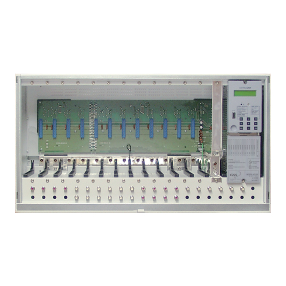
- Page 10 3.2 C o n n e C to rs a n d C o m p o n e n t s r o n t v i e w s i d e v i e w t y p e l a b e l Fig.
- Page 11 Fig. 4 HF output of the head-end station Mains connector Distributor for LNB operating voltage Openings for cable terminals Earth connection terminal, connection for potential equalisation Aeration openings e a r v i e w & Fig. 5 Aeration openings Cord grip of the mains connection cable &...
- Page 12 3.3 C o n t r o l u n i t £ ¡ ™ Fig.6 LC display Control to set the contrast of the LC display. 9-pin D-SUB socket to update the operating software, to connect the ¡ HRCU 8 / RCU 1 management unit. Control buttons (control panel) ™...
- Page 13 ns ta l l i n G th e h e a d e n d s tati o n 4.1 emC r e G u l at i o n s e l e c t rom ag n e t i c Co m pat i b i l i t y To comply with the current EMC regulations, it is necessary to connect the lines leading in and out of the head-end station (e.g. Cinch, HF) using standard cable terminals.
- Page 14 • Unlock the lock (fig. 8). • Slide the front cover upwards and unhook it. 4.3 m o u n t i n G t h e h e a d e n d s tat i o n – Install the head-end station vibration-free. Avoid, for example, mounting the head-end station onto a lift shaft or any other wall or floor construction that vibrates in a similar way.
- Page 15 • Mount the fastening screws at the wall and check for a secure hold. • Hang the head-end station onto the screws. o u n t i n G C a b i n e t In cabinets a circular aeration (e.g. by means of ventilators) is to be ensured. In addition it is necessary to permanently control the ambient temperature of max.
- Page 16 n s t a l l i n G C a s s e t t e Before installing or changing a cassette unplug the power cable of the head- end station from the mains power socket. Fig. 10 • Remove the fastening screws of an unoccupied slot from the bracket of the head-end station.
- Page 17 o w e r s u p p l y 6.1 sat if i n p u t d i s t r i b u to r See figures 11 and 12 for the power supply for the SAT IF input distributors. The power distributor (fig.
- Page 18 o n n e C t i n G t h e h e a d e n d s t a t i o n 7.1 (pe) ot e n t i a l e q ua l i sat i o n Equalise the potential (PE) in accordance with IEC/EN/DIN EN 50083 and IEC/EN/DIN EN 60728.
- Page 19 sat if o n n e C t i n G i n p u t s The following description refers to one of the SAT IF input distributors. The other SAT IF input distributors are connected in the same manner. •...
- Page 20 7.4 m a i n s C o n n e C t i o n To maintain compliance with current EMC regulations (electromagnetic com- patibility), it is necessary to route the power cord through the supplied & ferrite sleeve ≤ Mount the ferrite sleeve as near as possible to the housing of the head-end station (fig. 16).
-
Page 21: The Control Panel At A Glance
e t t i n G t h e C o n t r a s t t h e d i s p l a y • Adjust the contrast of the display using the controller £ ¡ ™ C o n t r o l p a n e l G l a n C e... -
Page 22: Updating The Software Of The Control Unit
10 u p d a t i n G t h e s o f t w a r e t h e C o n t r o l u n i t 10.1 u p dat i n G s o f t wa r e v i a The RS 232 interface of the control unit enables you to use a PC or a notebook... -
Page 23: Programming Slave Control Unit
r o G r a m m i n G s l av e C o n t r o l u n i t • Switch off the head-end station of the slave control unit. • Connect the 15-pin D-SUB plug on the back of the master control unit to the RS 232 interface of the head-end station’s slave control unit via a connec- tion cable made on-site as follows. -
Page 24: Preparation
n s e r t i n G m a s t e r C o n t r o l u n i t § • Connect control unit to the snap-in hook § • Push the control unit towards the head-end station, in the direction opposite that of arrow "... -
Page 25: Programming Procedure
11.2 p ro G r a m m i n G pro C e d u r e Ein / On BE–Remote V 45 please wait … t > 10 s t > 10 s Box … – – – Page 26 –... - Page 26 STATION NUMBER: SYSTEM MODEM: ON / OFF Page 25 SYSTEM SECURE: ◀ ▶ PASSWORD 0000 es saG e a f t e r t e m p e r at u r e e xC e e d i n G Instead of the standby "BE-Remote"...
-
Page 27: Activating System Information
11.3 p r o G r a m m i n G t h e h e a d e n d s tat i o n —> Pressing the button for longer than 2 seconds cancels the programming procedure. This takes you back to the program item "Activating system information"... -
Page 28: System Information - Output Collector
C t i vat i n G s ys t e m i n f o r m at i o n Box … – – – – – – – – – • Activate the "System information" software by simultaneously holding down the buttons for more than 2 seconds in the "Selecting the cas- sette"... -
Page 29: System Information - Temperature
– ys t e m i n f o r m at i o n o u t p u t C o l l e C to r This menu shows the software version of the output collector (e.g. "V 1"). SYSTEM INFO: Output-Coll. -
Page 30: System Information - Clock Frequency
– ys t e m i n f o r m at i o n n u m b e r t h e h e a d e n d s tat i o n This menu shows the number of the head-end station (see also item "Setting the consecutive number of the head-end station", page 31). -
Page 31: Setting The Hf Output Level Of The Head-End Station
and equal their HF output levels to the value of the cassette with the lowest HF output level using the buttons ("0 … -25 dB") • Press the button. —> The "Setting the HF output level of the head-end station" – "STATION LEVEL:" menu is activated. hf e t t i n G t h e... -
Page 32: Setting The Password
C t i vat i n G t h e m o d e m C o n n e C t i o n If the head-end station is to be remote controlled using the PSW 1000 con- figuration software and a modem connected to the head-end station (without HRCU 8 / RCU 1) activate the modem mode in this menu ("ON"). -
Page 33: Saving Settings
av i n G s e t t i n Gs • Press the button. —> The settings are saved. —> You return to the "Activating system information" menu item (page 28). —> By pressing the button, you will be returned to the menu item "System information –... - Page 34 – s ys t e m i n f o r m at i o n In this menu, the inner temperature is displayed which activated the lock (e.g. "68 °C") and the highest inner temperature recorded to date (e.g. "84 °C"). The inner temperature which activated the lock must be deleted to reactivate the temperature monitor and the software.
-
Page 35: Final Procedures
12 f i n a l pro C e d u res After installing the head-end station, upgrading accessories or installing cas- settes it is necessary to tighten all cable connections, cable terminals and cover screws in order to maintain compliance with current EMC regulations securely. • Securely tighten the cable connections (Cinch, HF connectors) using an ap- propriate open-ended spanner. • Hang the front cover into the locators • Push the front cover downward and close the lock The EMC seal of the front cover must fit tightly against the head-end station’s housing. - Page 36 Telefon: +49 (0) 911 / 703 8877 • Fax: +49 (0) 911 / 703 9210 www.gss.de • info@gss.de CLASS CLASS Kundendienst: Telefon: +49 (0) 911/703 2221; Fax: +49 (0) 911/703 2326; service@gss.de Änderungen vorbehalten. Technische Angaben ohne Gewähr. © by GSS Grundig Systems GmbH V45/001/2017...
Need help?
Do you have a question about the STC 1200 and is the answer not in the manual?
Questions and answers