Table of Contents
Advertisement
Quick Links
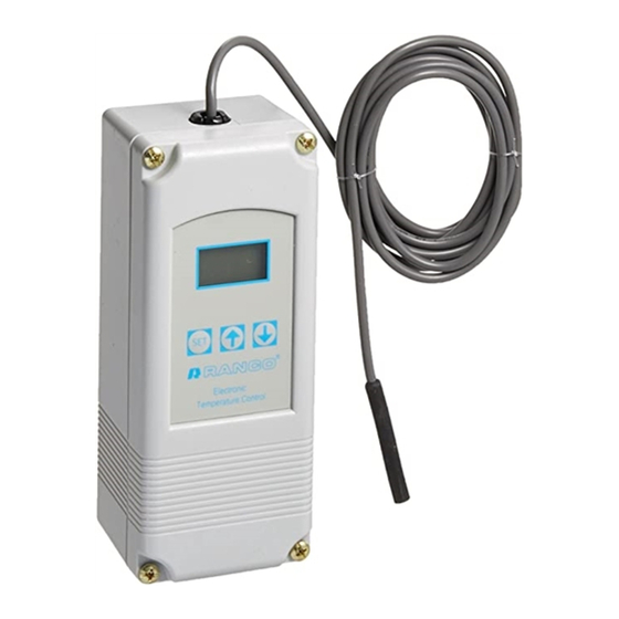
The Ranco® ETC is a microprocessor
based family of electronic temperature
controls, designed to provide on/off
control for commercial heating, cooling,
air conditioning and refrigeration. The ETC
is equipped with a liquid crystal display
(LCD) that provides a constant readout
of the sensed temperature, and a touch
keypad that allows the user to easily and
accurately select the setpoint temperature,
differential and heating/cooling mode
of the operation. Models are available
that operate on either line voltage
(120/208/240V AC) or low voltage (24V AC).
APPLICATIONS
With its wide temperature setpoint range
and selectable heating or cooling modes,
the ETC can be used for a wide variety of
applications including multiple compressor
control, two stage heating, ventilation
control, automatic changeover, condenser
fan cycling, space and return air tempera-
ture control, water cooled condensers and
control with alarm function.
FEATURES
• Wide setpoint temperature range (-30°F to 220°F) and differential
adjustment (1°F to 30°F)
• Simple keypad programming of setpoint temperature, differential and
cooling/heating modes
• Two individually programmable stages for heating and/or cooling
• LCD display readout of sensor temperature, control settings, relay
status and onboard diagnostics
• LED (Light Emitting Diode) backlight to improve visibility of the display
in low light ambient applications.
• IP67 rated (water and dust resistant) thermistor-based probe to
remotely monitor temperature
• The sensor probe can be retrofitted in the field by the use of factory
installed interconnect
• Remote temperature sensing up to 400 feet
• Two SPDT output relays
• User-selectable Fahrenheit/Celsius scales
• Lockout switch to prevent tampering by unauthorized personnel
• Choice of line voltage and low voltage models available
• Optional 0 to 10 volt analog output available for remote temperature
indication
• Anti-short Cycle Compressor Delay for cooling applications
Input Voltage
120 or 208/240V AC (24V AC optional), 50/60 Hz
Temperature Range
-30°F to 220°F
Differential Range
1°F to 30°F
Switch Action
SPDT
Sensor
Thermistor, 1.94 in. long x 0.25 in. diameter
with 8 ft. cable, IP67 rated
Power Consumption
120/208/240V AC: 100 milliamps
24V AC: 2-6V AC
INSTALLATION DATA
ETC TWO STAGE ELECTRONIC
TEMPERATURE CONTROL
Relay Electrical Ratings
NO Contact
Full-load amps
Locked rotor amps
Resistive amps
Horsepower
NC Contact
Full-load amps
Locked rotor amps
Resistive amps
Horsepower
Pilot Duty: 125 VA at 120/208/240 VAC
Control Ambient Temperature
Operating
Storage
Ambient Humidity
0 to 10V Output Impedance 1 K
Enclosure
Agency Approvals
ETC ORDERING INFORMATION
Uni-Line
OEM
Numbers
Numbers
ETC-211000-000
ETC-211020-000
ETC-211100-000
ETC-211120-000
ETC-212000-000
ETC-212020-000
ETC-212100-000
ETC-212120-000
OPERATION
Liquid Crystal Display (LCD)
The LCD display provides a constant readout of the sensor temperature
and indicates if either of the two output relays is energized. When the
S1 annunciator is constantly illuminated during operation, the Stage 1
relay is energized. Likewise, when the S2 annunciator is constantly
illuminated during operation, the Stage 2 relay is energized. The display
is also used with the keypad to allow the user to adjust the setpoint
temperatures, differentials and heating/cooling modes for each stage.
Backlight
When any mode key is pressed, the backlight is activated and the ETC is
in control mode. Press the SET key to begin program mode.
Control Setup
The temperature setpoint refers to the temperature at which the
normally open (NO) contacts of the output relay will open. Determine
the loads to be controlled and the operating modes required for each
stage, cooling or heating.
• When the cooling mode is chosen, the differential is above the setpoint.
The relay will de-energize as the temperature falls to the setpoint.
• Anti-short Cycle Compressor Delay for cooling. After a relay
de-energizes, the ETC will prevent the relay from turning on until a
configurable time has occurred to protect compressor.
• When the heating mode is chosen, the differential is below the setpoint.
The relay will de-energize as the temperature rises to the setpoint.
The ETC two stage control can be set up for two stages of heating, two
stages of cooling or one stage cooling plus one stage heating. Refer to
Figures 1, 2 and 3 for a visual representations of different control setups.
1
120V
208/240V
9.8 Amps
4.9 Amps
58.8 Amps
29.4 Amps
9.8 Amps
4.9 Amps
1/2 HP
1/2 HP
5.8 Amps
2.9 Amps
34.8 Amps
17.4 Amps
5.8 Amps
2.9 Amps
1/4 HP
1/4 HP
-20°F to 140°F (-29°C to 60°C)
-40°F to 176°F (-40°C to 80°C)
0 to 95%, RH, Non-condensing
NEMA 1, Plastic
UL Listed, File E94419, Guide XAPX
CSA Certified, File LR68340, Class 4813 02
Input
No. of
Voltage
Stages
120/240
2
120/240
2
24
2
24
2
0 - 10 V
Output
No
Yes
No
Yes
Advertisement
Table of Contents

Related Manuals for Ranco ETC Series


Summary of Contents for Ranco ETC Series
- Page 1 INSTALLATION DATA ETC TWO STAGE ELECTRONIC TEMPERATURE CONTROL Relay Electrical Ratings The Ranco® ETC is a microprocessor based family of electronic temperature NO Contact 120V 208/240V controls, designed to provide on/off Full-load amps 9.8 Amps 4.9 Amps control for commercial heating, cooling, Locked rotor amps 58.8 Amps...
- Page 2 Step 3 Press the SET key again to access the stage 1 differential. The LCD will display the current differential and the DIF 1 annunciator will be blinking on and off to indicate that the control is in the differential mode. Then press either the up Ç...
- Page 3 Program Mode Displays Step Annunciator Description Display LOCKOUT : LOCK UNLOCK F or C Fahrenheit or Celsius RELAY RATINGS N.O /N.C. DISPLAY CODES Scale 120 208/240 FAHRENHEIT LRA 96/34.8 48/17.4 CELSIUS H1 HEAT STAGE 16/5.8 8/2.9 S1 (blinking) Stage 1 Setpoint C1 COOL STAGE RES A...
- Page 4 CAUTION PRÉCAUTIONS Read all of the information in these instructions before installing Lire toutes les informations contenues dans ces instructions avant or operating the ETC control. d’installer ou d’utiliser le contrôleur ETC. The schematic drawings and other information included in these Les schémas et toutes les autres informations figurant dans ces installation instructions are for the purpose of illustration and instructions d’installation sont indiqués à...
- Page 5 FIELD REPAIRS Field calibrating or repairs to the ETC control must not be attempted. Figure 6: Typical Voltage Wiring Diagram. Sensors and replacement controls are available through Ranco wholesalers. SENSOR MOUNTING For space sensing, mount the sensor where it will be unaffected by heat/cool discharge or radiated heat sources.
- Page 6 Resistance vs Temperature Sensor including 8 foot cable. Replacement Sensor - Order Uni-Line Number 1309007-044 (OEM Number 1309007-048) Robertshaw®, Ranco®, Paragon® and Uni-Line® are trademarks of Robertshaw, its subsidiaries and/or www.robertshaw.com Customer Service Telephone 1.800.304.6563 For Technical Service affiliated companies. All other brands mentioned ©2018 Robertshaw...
Need help?
Do you have a question about the ETC Series and is the answer not in the manual?
Questions and answers