Advertisement
Quick Links
RAN
C 0
HC TWO ~
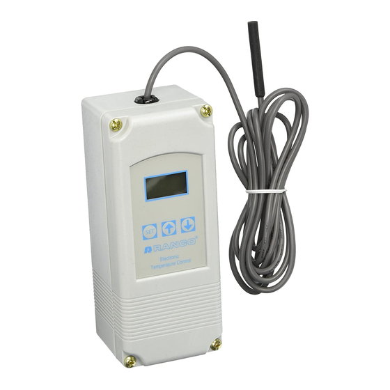
PRODUCT DESC
TheRa
i
of elee
em~~bUJe
provide
on/off
control
for
ing, air conditioning
and
equipped
with a liquid
provides a
constant readout of the sensed tem-
perature,
and a touch keypad that allows
to easily and accurately select the set point tem-
perature,
differential
and heating/cooling mode of
the operation.
Models
on either
line
voltage
(120/208/240
VAC)
or
compressor
control,
two
~--ventilation
control, automatic changeover,
space and
return air
temperature
/
I
with alarm
•
Wide setpoint
temperature
differential
adjustment (1°F to
•
Simple keypad programming
differential
and
coolinglheating
•
Two individually programmable stages for
and/or cooling.
•
LCD readout of sensor
relay status and onboard
•
Remote temperature sensing
•
Two SPOT
output relays.
•
User-selectable
Fahrenheit/Celsius
•
Lockout switch to prevent
personnel.
•
Choice of line voltage and
•
Optional
0 to 10
volt
temperature
indication.
Input Voltage
Temperature Range
Differential Range
Switch Action
Sensor
INS
TAL
COOircas,
e
refrigeration.
The
ETC
is
crystal display
(LCD)
that
the user
are available that
operate
I
I
stage
heating,
condenser fan cycling,
control,
water
cooled
condensers
funtion.
FEATURES
range (-30°F
to 220°F) and
30°F).
of
setpoint
temperature,
modes.
heating
temperature,
control
settings,
diagnostics.
up to 400
feet.
scales.
tampering by unauthorized
low
voltage models available.
analog output available
for
remote
120 or 208/240 VAC (24 VAC
optional),
-30°F to 220°F
1°F to 30°F
SPOT
Thermistor,
1.94 in. long x 0.25
in.
8
ft.
cable
120/208/240 VAC
:
100 milliamps
24 VAC:
2-6 VAC
~.
,'¢'.!"~~~,:.:.
.:r·
T'"I ~0
L'
N
~:
\.
CTR
HI(
T
NO Contact
Code
Number
ETC-211000-000
ETC-211100-000
ETC-212000-000
ETC·2121 00-000
Liquid Crystal Display (LCD)
The LCD display provides a
and indicates if either
annunciator
is constantly illuminated during
energized.
Likewise,
during
operation,
in
conjunction
temperatures, differentials and
Control Setup
The temperature
open (NO) contacts of the
be controlled and the
heating.
50/60 Hz
•
When the
cooling
The relay will de-energize as the temperature falls to the
•
When the heating mode is
The relay will de-energize as the temperature rises to the
diameter
with
The ETC two stage control can be set up for two stages of
of cooling or one stage cooling plus one stage heating. Refer to Figures
and 3 for a visual representations of different
INS
T
Rue
Full-load amps
9.8 A
Locked
rotor amps
58.8A
Resistive amps
9.8A
Horsepower
1/2 hp
.8A
5.8
A
1/4 hp
-20°F to 140°F (-29OC to 60OC)
-40°F to 176°F (-40OC to 80OC)
o
to
95%, RH,
!mpEldance
1
K
EMA
1.
Plastic
UL
·sted.
File
CSA
Certified, File
Input
Voltage
120/240
120/240
24
24
OPERATION
constant
readout
of
of
the two
output
relays is
operation,
when
the
S2
annunciator is constantly illuminated
the Stage 2 relay is
energized.
with the keypad to allow
the user to adjust the setpoint
heating/cooling modes for each
setpoint refers
to
the
temperature at which the normally
output
relay
will
open.
operating modes
required
mode is
chosen,
the
differential is above the
chosen,
the differential is below the
control
T ION
S
NTROl
4.9A
29.4 A
4.9A
1/2 hp
2.9 A
17.4
A
2.9A
1/4 hp
Non-condensing
E94419,
Guide XAPX
LR68340,
Class 4813 02
0-10 V
No. of
Stages
Output
No
2
2
Yes
2
No
2
Yes
the sensor temperature
energized.
When the
S1
the Stage
1
relay is
The display is also
used
stage.
Determine the loads to
for
each
stage,
cooling or
setpoint.
setpoint.
setpoint.
setpoint.
heating,
two stages
1,
2
setups.
Advertisement

Related Manuals for Ranco ETC


Summary of Contents for Ranco ETC
- Page 1 Sensor Thermistor, 1.94 in. long x 0.25 diameter with The ETC two stage control can be set up for two stages of heating, two stages cable of cooling or one stage cooling plus one stage heating. Refer to Figures 120/208/240 VAC...
- Page 2 ENERGIZED Programming Steps and Display OFF = DE-ENERGIZED The ETC two stage programmed seven simple steps using the LCD display and the three eys face control. programming, press the key once to access the STAGE 1 SETPOINT Fahrenheit/Celsius mode. The display will show the current...
-
Page 3: Troubleshooting Error Messages
INSTALLATION INSTRUCTIONS Lockout Switch IMPORTANT ---- 8~is provieJed with -a-lockotJt switch prevent-tampering--b All ETC series controls are designed as operating controls only. If an unauthorized personnel. When placed the LOCK position, operating control failure could result in personal injury or loss of... - Page 4 Caution should be exercised not to damage the control circuit board or Ranco assumes no responsibility for such use. wiring when installing a conduit connector. ANALOG OUTPUT (OPTIONAL)
-
Page 5: Analog Output
NC NO C NC C NO Figure 8: 0.10 V Analog Output Located on Power (Lower) Circuit Board. fiELD REPAIRS Field calibrating or repairs to the ETC control must not be attempted. Sensors and replacement controls are available through Ranco wholesalers... - Page 6 Additional cable can be spliced to the sensor cable to increase only. Ranco assumes no responsiblity unconventional length beyond the standard 8 feet. It can be extended up to 400 feet.
Need help?
Do you have a question about the ETC and is the answer not in the manual?
Questions and answers