
Related Manuals for PI L-505 Series

Summary of Contents for PI L-505 Series
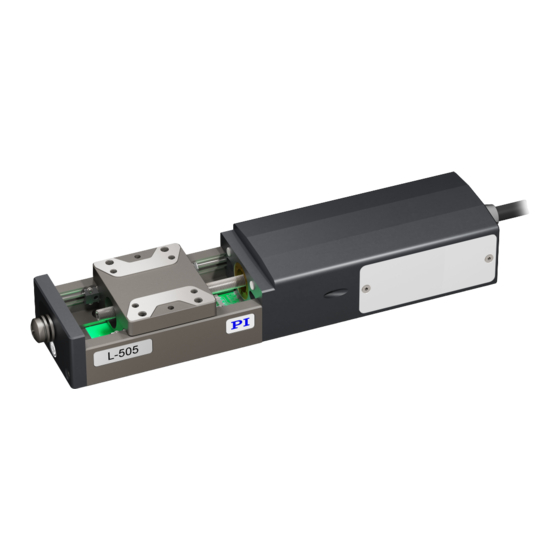
- Page 1 L505M0013EN ‒ 3/18/2020 User Manual L-505.021200 LINEAR STAGE WITH STEPPER MOTOR M O T I O N | P O S I T I O N I N G...
-
Page 2: Table Of Contents
CONTENTS L505M0013EN ‒ 3/18/2020 Contents Legal Information......................4 About this Document....................5 Objective and Target Group................5 Other Applicable Documents................5 Explanation of Symbols..................5 2.3.1 Typographic Conventions..............5 2.3.2 Symbols Used..................6 Figures........................ 6 Downloading Manuals..................6 Safety..........................8 Intended Use...................... 8 General Safety Instructions................8 Organizational Measures.................. - Page 3 CONTENTS L505M0013EN ‒ 3/18/2020 Troubleshooting......................28 10 Transportation......................29 11 Customer Service Department................. 30 12 Technical Data......................31 12.1 Specifications....................31 12.2 Maximum Ratings................... 33 12.3 Ambient Conditions and Classifications............33 12.4 Dimensions...................... 34 13 Old Equipment Disposal................... 35 14 Appendix........................36 14.1 Pin Assignment....................36 14.1.1 Drive Connector................
-
Page 4: Legal Information
With regard thereto, Physik Instrumente (PI) GmbH & Co. KG reserves all rights. The use of any text, images and drawings is permitted only in part and only when indicating the source. -
Page 5: About This Document
SMC Pollux Motion Controller The latest versions of the user manuals can be downloaded (p. 6) at www.pi.ws. Explanation of Symbols This chapter explains the symbols and markings used by PI in their user manuals. 2.3.1 Typographic Conventions Symbol / label Meaning... -
Page 6: Symbols Used
(p. 30). Downloading Manuals 1. Open the website www.pi.ws. 2. Search the website for the product number (e.g., P-882) or the product family (e.g., PICMA® bender). 3. Click the corresponding product to open the product detail page. - Page 7 2 ABOUT THIS DOCUMENT L505M0013EN ‒ 3/18/2020 5. Click the desired manual and fill out the inquiry form. ➔ The download link will then be sent to the email address entered. M O T I O N | P O S I T I O N I N G...
-
Page 8: Safety
► Always keep this user manual available with the L-505.021200. The latest versions of the user manuals can be downloaded (p. 6) at www.pi.ws. ► Add all information from the manufacturer such as supplements or technical notes to the user manual. -
Page 9: Product Description
4 PRODUCT DESCRIPTION L505M0013EN ‒ 3/18/2020 Product Description Product Labeling Figure 1: Product label on the L-505.021200 1. Type plate 2. Warning symbol: Electrostatic sensitive device 3. Protective earth connector 4. Warning symbol: Risk of crushing 4.1.1 Type Plate The type plate is on the plug connector of the L-505.021200. Figure 2: Type plate of the L-505.021200 1. -
Page 10: Scope Of Delivery
4 PRODUCT DESCRIPTION L505M0013EN ‒ 3/18/2020 Scope of Delivery Product number Description L-505.021200 Linear stage according to the order L505B1000 Mounting kit for mounting the L-505.021200, consisting of ■ 4 socket head screws, ISO 4762 M3×6 ■ 2 dowel pins, ISO 2338, 2h8×8 For securing extension cables: ■... -
Page 11: Suitable Electronics
4 PRODUCT DESCRIPTION L505M0013EN ‒ 3/18/2020 Drive screw The drive screw converts the rotary motion of the drive to linear motion of the motion platform. Limit switches The limit switches are sensors at each end of the travel range that enable the electronics to abort motion in order to prevent the motion platform from colliding with the mechanical hard stop. -
Page 12: Unpacking
5 UNPACKING L505M0013EN ‒ 3/18/2020 Unpacking Unpacking the L-505.021200 1. Unpack the L-505.021200 with care. 2. Compare the contents with the scope of delivery according to the contract and the delivery note. 3. Inspect the contents for signs of damage. If any parts are damaged or missing, contact customer service department (p. -
Page 13: Installation
6 INSTALLATION L505M0013EN ‒ 3/18/2020 Installation Mounting the L-505.021200 Overview Figure 4: Mounting the L-505.021200 onto an underlying surface Tools and Accessories Screw set for mounting the L-505.021200 (p. 10) ■ ■ Suitable screwdriver Requirements You have read and understood the general safety instructions (p. -
Page 14: Connecting The L-505.021200 To The Protective Earth Conductor
6 INSTALLATION L505M0013EN ‒ 3/18/2020 NOTICE Protruding screw heads! Protruding screw heads can damage the L-505.021200. ► Make sure that the screw heads are fully countersunk and cannot interfere with motion. NOTICE Excessively long screws and locating pins Screws and locating pins that are inserted too deeply can damage the L-505.021200. ►... -
Page 15: Setting Up A Multi-Axis System
6 INSTALLATION L505M0013EN ‒ 3/18/2020 Tools and Accessories ■ Suitable protective earth conductor: ■ Cable cross section ≥ 0.75 mm ■ Contact resistance <0.1 Ω at 25 A at all connection points relevant for attaching the protective earth conductor ■ Suitable screwdriver Requirements You have read and understood the general safety instructions (p. - Page 16 6 INSTALLATION L505M0013EN ‒ 3/18/2020 NOTICE Impermissibly high load on the positioners! In a multi-axis system, the stage used for the upper axis must also be moved. Impermissibly high loads impair the motion and can damage the positioners. ► Pay attention to the maximum permissible forces (p.
-
Page 17: Building A Vertical Multi-Axis System
6 INSTALLATION L505M0013EN ‒ 3/18/2020 Building a Vertical Multi-Axis System The L-505.021200 can be used as Z axis. An adapter bracket is necessary, refer to Optional Accessories (p. 11). Designations in these instructions: ■ Horizontal positioner: Forms the horizontal axis of the multi-axis system ■... - Page 18 6 INSTALLATION L505M0013EN ‒ 3/18/2020 Z Mounting Overview The adapter bracket for the L-505 can be attached in two different configurations. Requirements You have read and understood the general safety instructions (p. ✓ The positioners are not connected to the electronics. ✓...
- Page 19 6 INSTALLATION L505M0013EN ‒ 3/18/2020 NOTICE Damage due to mechanical stress on the cable! The cable will break from excessive or repeated bending. A broken cable will lead to failure of the L-505.021200 or damage to the L-505.021200 or the electronics. ►...
- Page 20 6 INSTALLATION L505M0013EN ‒ 3/18/2020 2. Attach the upper L-505 to the adapter bracket. a) Insert two locating pins into the adapter bracket. b) Align the L-505 to the adapter bracket. c) Insert the screws into the mounting holes in the upper L-505 and tighten them. M O T I O N | P O S I T I O N I N G...
-
Page 21: Mounting The Load Onto The L-505.021200
6 INSTALLATION L505M0013EN ‒ 3/18/2020 Mounting the Load onto the L-505.021200 Overview Figure 6: Mounting the load onto the L-505.021200 1. Screws M O T I O N | P O S I T I O N I N G... - Page 22 6 INSTALLATION L505M0013EN ‒ 3/18/2020 2. Load 3. Motion platform of the L-505.021200 Tools and Accessories ■ At least 3 screws with suitable dimensions (p. 34) ■ Suitable tools for tightening the screws ■ Optional: 2 suitably dimensioned dowel pins as locating pins for aligning the load on the L-505.021200 Requirements You have read and understood the...
-
Page 23: Connecting The L-505.021200
► Make sure that the electronics support the drive type of the L-505.021200 and has been configured accordingly. ► Use cables from PI miCos only to connect the L-505.021200 to the electronics. ► Pay attention to correct pin assignment (p. -
Page 24: Startup And Operation
2. Configure the electronics for the L-505.021200 during startup: ■ If you are using a digital controller and PC software from PI: Click the Assign Type from ID Chip option (if available) in the PC software or select the entry in the positioner database that matches the L-505.021200 exactly. -
Page 25: Maintenance
8 MAINTENANCE L505M0013EN ‒ 3/18/2020 Maintenance NOTICE Damage due to improper maintenance! Improper maintenance can lead to misalignment and failure of the L-505.021200. ► Loosen screws only according to the instructions in this manual or the instructions of our customer service department (p. 30). -
Page 26: Cleaning
8 MAINTENANCE L505M0013EN ‒ 3/18/2020 2. Drive screw Auxiliary Materials Required ■ Lubricant for the drive screw: Isoflex Topas 30 ■ Lubricant for the guides: Klüberquiet BQ 72‑72 Relubricating Under laboratory conditions, it is only necessary to relubricate the L-505.021200 in exceptional cases. - Page 27 8 MAINTENANCE L505M0013EN ‒ 3/18/2020 2. Insert a hex key AF 1.5 into the face of the drive screw. 3. Turn the hex key as far as necessary. a) Turn the screwdriver clockwise to move the motion platform in the direction of the screw hole.
-
Page 28: Troubleshooting
► Defective electronics ► Check the electronics. Motion platform has triggered the limit ► If you are using a controller from PI: Switch on switch the servo mode for the affected axis again in the PC software. ► Command the axis to move away from the limit switch. -
Page 29: Transportation
10 TRANSPORTATION L505M0013EN ‒ 3/18/2020 Transportation Preparing the L-505.021200 for Transportation 1. Pay attention to the ambient conditions and classifications (p. 33). 2. Pack the L-505.021200 in the original packaging. 3. If the L-505.021200 is to be sent, use a stable outer box. M O T I O N | P O S I T I O N I N G... -
Page 30: Customer Service Department
L505M0013EN ‒ 3/18/2020 Customer Service Department For enquiries and orders, contact your PI miCos representative or send us an email. If you have any questions concerning your system, provide the following information: ■ Product and serial numbers of all products in the system ■... -
Page 31: Technical Data
12 TECHNICAL DATA L505M0013EN ‒ 3/18/2020 Technical Data 12.1 Specifications Unit Tole- L-505.021200 rance Active axes Motion and positioning Unit Tole- L-505.021200 rance Travel range Integrated sensor – Sensor signal – Sensor resolution µm – Design resolution µm 2.5 (full step) Minimum incremental motion µm Typ. - Page 32 12 TECHNICAL DATA L505M0013EN ‒ 3/18/2020 Mechanical properties Unit Tole- L-505.021200 rance Guide type Ball bearings Leadscrew Drive screw type Drive screw pitch Load capacity Max. Permissible lateral force Max. Push/pull force Max. Holding force, power off Typ. Permissible torque M in θ...
-
Page 33: Maximum Ratings
12 TECHNICAL DATA L505M0013EN ‒ 3/18/2020 Miscellaneous Unit Tole- L-505.021200 rance Operating temperature range °C 5 to 40 Material Anodized aluminum, stainless steel Mass ±5 % Moved mass ±5 % 0.07 Connector HD D-sub 26 (m) Cable length ±10 mm 0.5 C-663.12 (single axis) Recommended controllers SMC Hydra (double axis) -
Page 34: Dimensions
12 TECHNICAL DATA L505M0013EN ‒ 3/18/2020 12.4 Dimensions Figure 8: Dimensions of the L-505.021200 Dimensions in mm. Note that the decimal places are separated by a comma in the drawings. Figure 9: Motion platform of the L-505.021200: Dimensions and mounting holes Dimensions in mm. -
Page 35: Old Equipment Disposal
In order to fulfil the responsibility as the product manufacturer, PI miCos undertakes environmentally correct disposal of all PI miCos equipment free of charge, if it was made available to the market after August 13, 2005. Any old PI miCos equipment can be sent free of charge to the following address:... -
Page 36: Appendix
14 APPENDIX L505M0013EN ‒ 3/18/2020 Appendix 14.1 Pin Assignment 14.1.1 Drive Connector Figure 10: HD D-sub 26 (m) Function Input: Motor voltage, phase A, + Not connected Input: Motor voltage, phase A, - Not connected Input: Motor voltage, phase B, + Not connected Input: Motor voltage, phase B, - Not connected... -
Page 37: Drive Properties
14 APPENDIX L505M0013EN ‒ 3/18/2020 Function Not connected Not connected Ground Not connected 14.2 Drive Properties If you use third-party control electronics, it may be necessary to adapt the following operating parameters to the L-505.021200. Parameters L-505.021200 Unit Motor type 2-phase stepper motor Drive screw pitch 14.3... -
Page 38: Limit Switch Specifications
14 APPENDIX L505M0013EN ‒ 3/18/2020 14.4 Limit Switch Specifications Type Hall sensor Supply voltage +5 V Signal output Open collector Signal logic N/C contact: Limit switch inactive: Low resistance (0 V) Limit switch active: High resistance (+5 V) Figure 11: L-505 at the negative limit switch. Figure 12: L-505 at the positive limit switch. -
Page 39: Eu Declaration Of Conformity
15 EU DECLARATION OF CONFORMITY L505M0013EN ‒ 3/18/2020 EU Declaration of Conformity An EU Declaration of Conformity was issued for the L-505.021200 in accordance with the following European directives: ■ EMC Directive ■ RoHS Directive The applied standards certifying the conformity are listed below. ■... - Page 40 Each limit switch sends its signal to the controller on a dedicated line. The controller then interrupts the motion avoiding that the positioner moves until the hard stop and gets damaged. PI positioners have mechanical, noncontact optical or Hall-effect limit switches. Load Capacity Maximum load in the vertical direction when the L-505.021200 is mounted horizontally.
- Page 41 L505M0013EN ‒ 3/18/2020 Sensor resolution The sensor can be the critical element of position resolution so it may be necessary to specify the sensor resolution separately. Rotary encoder: Impulses per screw rotation. Linear encoder: Smallest motion still detected by the sensor system. Travel Range The maximum possible travel range is limited by the length of the drive screw.
Need help?
Do you have a question about the L-505 Series and is the answer not in the manual?
Questions and answers