
Related Manuals for schroff VXS64 Series

Summary of Contents for schroff VXS64 Series
- Page 1 VXS/VME64x Tower System User’s Manual Product No.: 10836-060 Doc-No: 63972-161_R1.1 May 04, 2009...
- Page 2 November 12, 2007 Initial Release R1.1 May 04, 2009 Technical data fans updated Impressum: Schroff GmbH D-75334 Straubenhardt, Germany The details in this manual have been carefully compiled and checked - supported by certified Quality Management System to EN ISO 9001/2000 The company cannot accept any liability for errors or misprints.
-
Page 3: Table Of Contents
Service ......................14 Technical support and Return for Service Assistance ........14 Declaration of Conformity .................. 14 Scope of delivery ....................15 Accessories ....................... 15 Spare Parts......................15 Technical Data ....................16 Dimensions ..................... 17 www.schroff.biz R1.1, May 04, 2009... - Page 4 VXS/VME64x Tower System 10836-060 www.schroff.biz R1.1, May 04, 2009...
-
Page 5: Safety
• the overall unit complies with all other regulations and specifications at the place and country of use, e.g. interference limits, approval by the telecom- munications authorities. www.schroff.biz R1.1, May 04, 2009... -
Page 6: Safety Instructions
It must therefore be operated only with protective GND/earth connection! • Service personnel must know the necessary electrical safety, wiring and connection practices for installing this equipment. • Install this equipment only in compliance with local and national electrical codes. www.schroff.biz R1.1, May 04, 2009... -
Page 7: References And Architecture Specifications
• User Manual Fan Control Module (FCM) Order no.: 73972-083 • User Manual Power Supply Order no.: 73972-077 • User Manual Power Backplane Order no.: 73972-072 For more information see the catalogue „Electronic Packaging“ and at www.schroff.biz www.schroff.biz R1.1, May 04, 2009... -
Page 8: Product Definition
Product Definition 10836-060 2 Product Definition The Schroff VXS/VME64x Tower System consists of: • A shielded subrack with front assembly area for 7 front boards (6 U, 160 mm deep) and rear assembly area for 7 Rear I/O boards (6 U, 80 mm deep) •... -
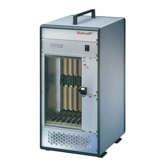
Page 9: Mechanical Overview
Front panel, perforated AC Switch Rear Fans 19“ Power Supply AC Connector (IEC320-C14) with filter and fuses Card Cage with Guide Rails VXS/VME64x Backplane Front panel 3 HE / 8 TE Fan Control Module (FCM) Front fans www.schroff.biz R1.1, May 04, 2009... -
Page 10: Tower System
10836-060 2.2 Tower System The VXS/VME64x Tower System system based on the Schroff europacPro subrack in a ratiopacPro chassis with EMC shielding. The front card cage provides space for the installation of 7 VXS/VME64x Boards (6 U, 4 HP, 160 mm deep), the rear card cage provides space for the installation of 7 Rear I/O Boards (6 U, 4 HP, 80 mm deep). -
Page 11: Power Supply
AC Connector Warning! The fuse value has been determined in factory for the maximum power delivered by the power supply. The fuse value must be changed to the actual current of the complete equipped system. www.schroff.biz R1.1, May 04, 2009... -
Page 12: Grounding
Recovery time to within 1% < 300 µsec Overvoltage protection for all voltages 120 – 130 % U > 5 V Overcurrent protection 105 – 130 % of rated output current Hold-up time >= 20 ms www.schroff.biz R1.1, May 04, 2009... -
Page 13: Wiring Diagram
+12V Anode -12 V Anode Fan Control Module Fan Fail Anode Tmp Fail Anode GND (Cath com) -12 V Cath. 3.3 V +12 V -12 V Backplane Power Supply 1 Power Supply 2 (optional) 10007800 www.schroff.biz R1.1, May 04, 2009... -
Page 14: Thermals
The NTC temperature sensor is located above the card cage. Caution! To maintain proper airflow, all open slots must be covered with filler panels. The filler panel should include an airflow baffle that extends to backplane. Figure 5: Airflow 10006053 www.schroff.biz R1.1, May 04, 2009... -
Page 15: Fan Control Module (Fcm)
Fan Speed Over-Temp. 10007807 For more information see the FCM’s User Manual, Order No.: 73972-083 and at www.schroff.biz 2.7 Display Module Figure 7: Display Module The Display Module is located at the upper front side of the subrack. 4 green LEDs signal the 4 VME64x voltages, two red LEDs signal over-temperature and fan fail events. -
Page 16: Installation
Caution! To maintain proper airflow, all open slots must be covered with filler panels. The filler panel should include an airflow baffle that extends to backplane. www.schroff.biz R1.1, May 04, 2009... -
Page 17: Basic Functional Check
The fuse value has been determined in factory for the maximum power delivered by the power supply. The fuse value must be adjusted to the actual current consumption of the completed system. Maximum value is 8 A slow blow. www.schroff.biz R1.1, May 04, 2009... -
Page 18: Service
10836-060 4 Service 4.1 Technical support and Return for Service Assistance For all product returns and support issues, please contact your Schroff sales distributor or www.schroff.biz. We recommend that you save the packing material. Shipping without the original packing material might void the warranty. -
Page 19: Scope Of Delivery
20848-7xx Filler panel with EMC front plate for empty Slots, dimensions see catalogue 34562-8xx Filler panel for empty Slots, dimensions see catalogue 24579-03x Printed Circuit Board covers, dimensions see catalogue 4.5 Spare Parts On request. www.schroff.biz R1.1, May 04, 2009... -
Page 20: Technical Data
2,2 kVDC Output - PE: 0,7 kVDC Output - Output: 0,7 kVDC Shock and Vibration: EN 60068-2-6 and EN 60068-2-27 Electromagnetic Shielding Shielding attenuation typ. 40 dB at 1 GHz if shielded front panels are used. www.schroff.biz R1.1, May 04, 2009... -
Page 21: Dimensions
VXS/VME64x Tower System Dimensions 10836-060 6 Dimensions Figure 8: Mechanical Dimensions 10007851 All dimensions in millimeters (mm). www.schroff.biz R1.1, May 04, 2009... - Page 22 VXS/VME64x Tower System Dimensions 10836-060 www.schroff.biz R1.1, May 04, 2009...
- Page 24 SCHROFF GMBH www.schroff.biz Langenalberstr. 96-100 Tel.: + 49 (0) 7082 794-0 Fax: +49 (0) 7082 794-200 D-75334 Straubenhardt...
Need help?
Do you have a question about the VXS64 Series and is the answer not in the manual?
Questions and answers