Table of Contents
Advertisement
Advertisement
Table of Contents
Troubleshooting

Related Manuals for LONCIN 900 Mini teller


Summary of Contents for LONCIN 900 Mini teller
- Page 2 Foreword Thank you for purchasing our mini tiller It is the accelerator for your building of a richer life. With a small size, a light weight, multiple functions, high rotary tilling efficiency, ability to work on mountains, in waters, to cross ridges of fields and ditches, and easy transport and operation of turning around, this model of mini tiller is especially suitable for work in mountain areas, hilly areas, arid fields, irrigated fields, orchards, gardens, arch-roofed sheds, etc.
-
Page 3: Table Of Contents
Thank you Contents Chapter I Safety warnings ………………………………………………………………………………4 Chapter II Safety symbols ………………………………………………………………………………8 Chapter III Brief introduction of mini tiller ……………………………………………………………10 i. Major technical parameters …………………………………………………………………… 10 ii.Names of major parts and components of mini tiller…………………………………………… 11 Chapter IV Operation method of the mini tiller …………………………………………………………12 i. - Page 4 iv. Long storage of mini tiller………………………………………………………………………22 Chapter VI Adjustment method of mini tiller……………………………………………………………22 i. Method of adjusting reverse cable ………………………………………………………………22 ii. Method of adjusting clutch cable ……………………………………………………………… 22 iii. Method of adjusting accelerator cable …………………………………………………………23 iv. Method of using and adjusting handle pipes ……………………………………………………23 Chapter VII Trouble shooting of mini tiller ……………………………………………………………...
-
Page 5: Chapter I Safety Warnings
Chapter I Safety warnings 1. Training a) Carefully read the operation manual. Get fully familiar with the correct method of operation of this machine and its mechanisms. Understand how to stop it and how to quickly disengage the operation mechanism. b) No child is allowed to use the machine! No adult is allowed to use the machine before carefully reading the manual! c) Ensure no other persons or things with potential safety risk, especially children and pets,... - Page 6 2) When the engine is running or is hot, never try to add fuel into it! 3) Take extra care when fueling the engine outdoors; never try to fuel the engine indoors! 4) Before starting, tighten the fuel tank cap and wipe off any fuel spilled out! e) Never try to make any adjustment when the engine is running! f) For any operation or work on the machine, for example, preparation and maintenance of the machine, wearing a pair of safety glasses is necessary.
- Page 7 between blades, always remember to shut off the engine first! g) If the machine is to be left uncared by the operator, all necessary preventive measures, such as disengaging power output shaft, lowering of accessory devices, shift to neutral position of gear shift lever, and shutting off the engine shall be taken first! h) Before cleaning, repair or checking the machine, the operator must shut off the engine and ensure all moving parts are in a stationary state!
- Page 8 pushing the mini tiller forward. If such a result does occur, just let free the handle and don’t try to control the machine! r)Never operate the mini tiller on an abrupt slope! s) Take care not to let the machine turn over when it is ascending or descending a slope! 4.
-
Page 9: Chapter Ii Safety Symbols
Chapter II Safety symbols The following symbols are to remind you that if you don’t pay attention, you might be severely injured. Please carefully read the symbols and notices about safety in the manual. If these symbols peel off or are illegible, please contact the distributor to replace such symbols. Figure 2-1 Figure 2-2 Figure 2-1 to be stuck on engine fuel tank... - Page 10 Figure 2-3 Figure 2-4 Figure 2-3 to be stuck on engine fuel tank Figure 2-4 to be stuck on engine air filter Figure 2-5 Figure 2-6 Figure 2-5 to be stuck on fender Figure 2-6 to be stuck on fender All the safety symbols conform to GB10396.
-
Page 11: Chapter Iii Brief Introduction Of Mini Tiller
Chapter III Brief introduction of mini tiller This product is made in compliance with JB/T10266.1-2001 Specification of Handheld Tillers, JB/T10266.2-2001 Testing Method for Handheld Tillers, GB/T5608.3-1995 Testing Method of Rotary Tillers, GB10395.10-2006 Tractors and Machinery for Agriculture and Forestry―Technical Means for Ensuring Safety and DB50/210-2005 Technical Means for Ensuring Safe Operation of Handheld Tillers. -
Page 12: Ii.names Of Major Parts And Components Of Mini Tiller
Item name Parameters Corresponding power G200F Maximum theoretical power kW (r/min) 3.4/3600 Weight (without rotary tilling device) (kg) External size (L×W×H) ( mm) 1450×900×1000 /h.m ≥0.04 Productivity/hour ≥400 Productivity Rotary tilling ≥100 Tilling depth Rotary tilling (mm) Tilling width Rotary tilling (mm) 600~1000 Forward (m/s) -
Page 13: Chapter Iv Operation Method Of The Mini Tiller
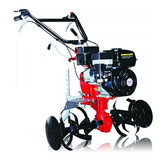
Figure 1 1. Handle pipe assembly 2. Engine assembly 3. Damping lever 4. Transmission box assembly 5. Fender 6. Tilling blade assembly 7. Damping lever assembly Chapter IV Operation method of the mini tiller i. Assembly after unpacking... -
Page 14: Installation And Adjustment Of Cables
1. Secure the main engine and insert the output shaft into the hexagon hole of the transmission countershaft in the lower part of the transmission box. 2. Installation of shaft and wheel: install the wheels onto both ends of output shaft and use 2 locking pin assemblies to secure them. - Page 15 Figure 2 Figure 3 Clutch cable Supporting block Reverse cable Cable lug Fork shaft Figure 4 2. Adjustment of reverse cable (see Figure 3 and Figure 4) 1) Loosen the nut around the reverse cable. 2) Turn clockwise the screw until its exposed part from the handle pipe is of its shortest length. 3) Insert the reverse cable into the fork shaft on one side of the transmission box and make sure the front end of the reverse cable is in the big hole of the fork shaft.
-
Page 16: Check And Oiling
opening of the cable lug on one side of the transmission box, make sure the front end of conduit is in the big hole of the cable lug. 5) Loosen out the screw and grip it firmly several times, then release the reverse shift handle, when the spring tension can return the position of the reverse shift handle, tighten the nut.3. - Page 17 Bolt to secure engine bracket and engine 35~40 2. Check whether handles of operating system, namely the handles for accelerator, clutch, gear shift, and reverse shift can work freely, and whether any of them cannot reach any required position, if so, check to repair it.
- Page 18 Oil number Figure 6 Recommended numbers Extreme usable numbers Table 1 Temperatu 6) Fill air filter with engine oil. Detach the lower cover of air filter and add in about 0.1 liter of SAE15W-40 engine oil. 7) Select the number of engine oil according to the ambient temperature of the working environment (see Table 1).
-
Page 19: Starting
6. Prepare the engine as required by engine manual before starting it. iv. Starting Note: shift lever must be in the neutral position. 1. Start the engine by following the steps specified in the engine manual. 2. Run the engine at the idle speed (1800±150 r/min) without load for 2 to 3 minutes. 3. -
Page 20: Connection And Operation Of Attached Parts
2) Right hand puts the shift lever to “neutral” position, take care to ensure it does reach “neutral” position, then slowly tighten your grip on the reverse shift handle. 3) Slowly tighten your grip on clutch handle to let the clutch engage, then mini tiller will run backward (note: don’t release the reverse shift handle). -
Page 21: Precautions For Use Of Mini Tiller
the field. vii. Precautions for use of mini tiller 1. Observe the working status of different parts and carefully listen to the machine’s sound, check to see if connections of different parts are normal, because loose connection is not allowed. If any abnormal condition is found, the operator should stop and check. -
Page 22: Technical Maintenance Of Mini Tiller
hours under a light load, and when the engine is still warm, drain all engine oil in the crankcase of the diesel engine. Fill the engine with engine oil and run it for 4 hours for running in, then the machine can be used for normal farming. -
Page 23: Long Storage Of Mini Tiller
② Ask repair and maintenance professionals to check friction disks and clutch. 5. Repair and maintenance of engine shall be conducted as per the engine’s manual. iii. Schedule of mini-tiller’s technical maintenance (an item marked with ● shall be maintained) Work Time After 8 hours of After the first... -
Page 24: Chapter Vi Adjustment Method Of Mini Tiller
and erosion. 1. Seal up and store the engine as per requirements in the manual of engine. 2. Clean dirt and grime on the outer surface, 3. Drain lubricant from the transmission box and fill it with new lubricant. 4. Apply anti-corrosion oil on unpainted part of the non-aluminum-alloy surface. 5. -
Page 25: Method Of Adjusting Accelerator Cable
clutch. If it is abnormal, readjust the clutch. 2. If the clutch’s work is still abnormal after several times of adjustment, it can be confirmed that the wear of clutch forks or friction disks is too heavy, and the mini tiller’s friction disks or clutch forks shall be replaced with new ones by an authorized service shop. - Page 26 1) Release the lifting handle, let handle pipe adjusting tooth disc be able to be adjusted up and down against the handle pipe connecting part. 2) Select the position of handle pipes according to your height and habit. 3) Turn the lifting handle, let handle pipe adjusting tooth disc engage with the teeth on the upper side of the handle pipe connecting part, and secure the handle pipes.
-
Page 27: Chapter Vii Trouble Shooting Of Mini Tiller
Chapter VII Trouble shooting of mini tiller i. Trouble shooting of clutch (note: never try to detach the clutch assembly by your self, if you find any of the malfunctions marked with ※ in the table below, please contact our company or the distributor) Phenomenon Cause Solution... -
Page 28: Trouble Shooting Of Transmission Box
ii. Trouble shooting of transmission box Phenomenon Cause Solution Detach the main shaft’s back-end bolt, Gear engagement in fast, Back-end bolt of main shaft is loose and protecting bush, retighten the round nut slow and neutral positions the round nut is loose and then refit the protecting bush and are not reliable bolt, and retighten them... - Page 29 Deformation of reverse shaft Replace reverse shaft Back-end bolt of reverse shaft is loose Retighten back-end bolt of reverse shaft Reverse shaft is loose Fit between reverse shaft and transmission Replace box is too loose Countershaft or reverse shaft is deformed Replace bent shaft or bent Gear wear is too heavy, which makes...
-
Page 30: Trouble Shooting Of Running Mechanism
iii. Trouble shooting of running mechanism Phenomenon Cause Solution Too high noise from gear Too heavy wear or incorrect repair of Reinstall, adjust or replace gear gear Seizure of gear during its Incorrect installation Reinstall it rotation Overheating Lubricant inside Add engine oil as required insufficient Lateral clearance of gear is too small... -
Page 31: Trouble Shooting For Other Parts
iv. Trouble shooting for other parts Phenomenon Cause Solution Blade hits stones, bricks Replace broken blade and take Rotary tilling blade is broken or other hard objects care to avoid blade’s clashing during working with stones or other hard objects in soil Operating cable is broken Wear caused by long Replace operating cable...
Need help?
Do you have a question about the 900 Mini teller and is the answer not in the manual?
Questions and answers