Table of Contents
Advertisement
Quick Links
Thanks for purchasing a Small Wonder Labs "Retro-40" transceiver kit!
Please take a few moments to look over the sections entitled "First Things First" before
you dive in. This section contains information which is key to your success with this kit.
'Retro-40' Instructions
'Retro-40' AM Transceiver
Board Kit Instructions
For illustrative purposes only- do not use as a reference.
TABLE OF CONTENTS:
Troubleshooting the "Retro-40 " [under construction]
July 11, 2011
2,3
4
5,6
7, 8
9-10
11
12
14
15-16
Page 1
Advertisement
Table of Contents

Related Manuals for Small Wonder Labs Retro-40


Summary of Contents for Small Wonder Labs Retro-40
-
Page 1: Table Of Contents
Board Kit Instructions For illustrative purposes only- do not use as a reference. Thanks for purchasing a Small Wonder Labs "Retro-40" transceiver kit! Please take a few moments to look over the sections entitled "First Things First" before you dive in. This section contains information which is key to your success with this kit. -
Page 2: Tools/Basic Info
RETRO-40 Power Requirements Touch the soldering iron tip to the PC board trace and the component lead simultaneously. The RETRO-40 is designed to operate with a Within a second or two, apply solder and you'll minimum supply voltage of approximately 10V. A see the solder flow onto the junction. - Page 3 MATERIALS- clean. It may be necessary to pull the component out from the top side of the board while heating You'll find the following items with your Retro-40 the joint. Leave the iron tip on the board only as kit:...
-
Page 4: Component Identification
'1458' or other markings I've specified If I've specified a capacitor '104' and you find the correct number of parts, but marked "104M', for instance, those are them! D5- MV1662 Diode Here's general rule capacitor nomenclature: ‘Retro-40’ Instructions July 11, 2011 Page 4... -
Page 5: 'Retro-40 ' Description
‘Retro-40 ‘ Description Note: The text which follows describes the original (75M) Retro version. For the 40M version , the IF is changed from 6 MHz to 4.915 MHz, and tuned circuits and the output low-pass filter values are changed. The operating frequency is in the 7.0-7.3 MHz range. - Page 6 DC voltage. Based on the DC reading, the builder can compensate with a ‘select’ capacitor to bring the oscillator on frequency. See the ‘Alignment’ section of these instructions for further details. ‘Retro-40 Instructions July 11, 2011 Page 6...
-
Page 7: Parts List
‘Retro-40’ Parts List Qty. Ref. Designator Description Identification C3-A,C22 22 pF NPO disk ‘22’ 6-30 pF trimmer Green C8-C11 33 pF NPO disk ‘33J’ C1,C2,C3-B 47 pF NPO disk ‘47J’ C3-C 68 pF NPO disk ‘68J’ C3-D, C4,C12,C13,C34-C36 100 pF NPO disk ‘101J’... - Page 8 ‘Retro-40’ Parts List (cont’d) R31,R32 47K ohm “ Ylw-viol-org-gold R10, R12, R13, R15, R20, R28, R35 100K ohm “ Brn-blk-ylw-gold 220K ohm “ red-red-ylw-gold R1, R7 1M ohm “ Brn-blk-grn-gold T1,T2 IF transformer metal can-‘42IF123’ Audio transformer ‘TU048-R’ SA612AN IC U2, U7 78L06 –...
- Page 9 ‘Retro-40 Instructions July 11, 2011 Page 9...
- Page 10 1.38 uH 1.38 uH 7.122 220K T44-2, 16T T44-2, 16T T44-2, 18T ANT. 1412N (Y5) 2.2K IRF530A 100K 2.2K D11 D12 C113 C114 40M AM Transceiver - p.2 of 2 7/11/2011 Dave Benson, K1SWL ‘Retro-40 Instructions July 11, 2011 Page 10...
-
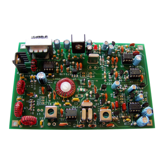
Page 11: Pictorial Drawing
‘Retro-40 Instructions July 11, 2011 Page 11... -
Page 12: Schematics
(cathode) end of the diode is always at the top. For diodes which are installed 'lying down', match the banded end to that shown on the silkscreen and pictorial illustration. Banded end Is cathode Diode- Schematic Pictorial • Resistor installation: ‘Retro-40 Instructions July 11, 2011 Page 12... - Page 13 This kit includes a pair of heat sinks and 4-40 steel hardware- install these on the power semiconductors and • tighten down. ‘Retro-40 Instructions July 11, 2011 Page 13...
-
Page 14: Wiring Up The Retro-40
Toroidal inductor L1 should be restrained on the printed-circuit board using the nylon screw, nut and shoulder- • washer supplied with the kit. This improves mechanical stability and reduces the chance of ‘microphonics’. Wiring up the Retro-40: ANTENNA DC POWER... -
Page 15: Alignment
Alignment Instructions: There are 3 alignment steps for the Retro-40- these should be performed in the order given below. 1) Local Oscillator frequency 2) Receiver IF peaking 3) Receiver RF peaking The tolerances on analog oscillator components (typically +/- 5%) mean that after assembling the oscillator, its operating frequency is uncertain. - Page 16 ‘highs’ in your signal, decrease the value of R19 and scale the value of C25 upward by the same factor. The Retro-40’s carrier output power is 2 Watts. With audio modulation, the peak envelope power is 7-8 watts. The Retro-40 complies with current FCC requirements for waveform spectral purity.
- Page 17 The ceramic (piezoelectric) microphones provide high-level audio but require no working bias voltage. The classic D-104 microphone is the most familiar example of this type. Add a 100K-220K resistor in series with the microphone input. This reduces the Retro-40 audio gain to comfortable levels. Electret Microphones: Not recommended.
Need help?
Do you have a question about the Retro-40 and is the answer not in the manual?
Questions and answers