Table of Contents
Advertisement
Quick Links
Thanks for purchasing a Small Wonder Labs "Retro-75" transceiver kit!
Please take a few moments to look over the sections entitled "First Things First" before
you dive in. This section contains information which is key to your success with this kit.
'Retro-75' Instructions
'Retro-75' AM Transceiver
Board Kit Instructions
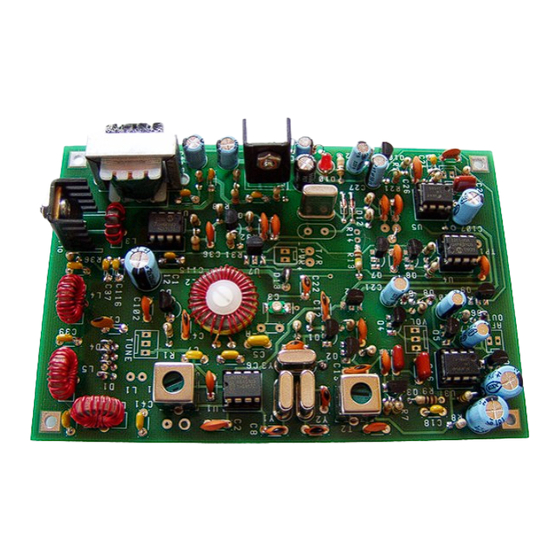
For illustrative purposes only- do not use as a reference.
TABLE OF CONTENTS:
Troubleshooting the "Retro-75 " [under construction]
Jan. 18, 2011
2,3
4
5,6
7, 8
9-10
11
12
14
15-16
Page 1
Advertisement
Table of Contents

Related Manuals for Small Wonder Labs Retro-75


Summary of Contents for Small Wonder Labs Retro-75
-
Page 1: Table Of Contents
Board Kit Instructions For illustrative purposes only- do not use as a reference. Thanks for purchasing a Small Wonder Labs "Retro-75" transceiver kit! Please take a few moments to look over the sections entitled "First Things First" before you dive in. This section contains information which is key to your success with this kit. -
Page 2: Tools/Basic Info
RETRO-75 Power Requirements good joint. A small vise to hold the printed-circuit board may make soldering easier. The RETRO-75 is designed to operate with a minimum supply voltage of approximately 10V. A Touch the soldering iron tip to the PC board trace and the component lead simultaneously. - Page 3 MATERIALS- out from the top side of the board while heating the joint. Leave the iron tip on the board only as You'll find the following items with your Retro-75 long as necessary to do the job- the PC-board kit: traces will eventually delaminate (peel off) if overheated.
-
Page 4: Component Identification
'1458' or other markings I've specified If I've specified a capacitor '104' and you find the correct number of parts, but marked "104M', for instance, those are them! D5- MV1662 Diode Here's general rule capacitor nomenclature: ‘Retro-75’ Instructions Jan. 18, 2011 Page 4... -
Page 5: 'Retro-75 ' Description
‘Retro-75 ‘ Description Inspirations: I’ve long been intrigued by relatively simple voice radios. The BC-611/SCR-536 [at right] was widely used during WW II as a platoon-level radio. It had a ‘bare-bones’ crystal-controlled superhet receiver and an AM transmitter with 350 milliwatts of output power. It had an effective range of about a mile with its built- in whip antenna. - Page 6 DC voltage. Based on the DC reading, the builder can compensate with a ‘select’ capacitor to bring the oscillator on frequency. See the ‘Alignment’ section of these instructions for further details. ‘Retro-75 Instructions Jan 18, 2011 Page 6...
-
Page 7: Parts List
‘Retro-75’ Parts List Qty. Ref. Designator Description Identification C3-A,C22 22 pF NPO disk ‘22’ 6-30 pF trimmer Pre-installed C8-C11 33 pF NPO disk ‘33’ or ‘33J’ C3-B 47 pF NPO disk ‘47’ C3-C 68 pF NPO disk ‘68’ 82 pF NPO disk ‘82’... -
Page 8: Revision History
‘Retro-75’ Parts List (cont’d) R31,R32 47K ohm “ Ylw-viol-org-gold R10, R12, R13, R15, R20, R28, R35 100K ohm “ Brn-blk-ylw-gold 220K ohm “ red-red-ylw-gold R1, R7 1M ohm “ Brn-blk-grn-gold T1,T2 IF transformer metal can-‘42IF123’ Audio transformer ‘TU048-R’ SA612AN IC... - Page 9 ‘Retro-75 Instructions Jan 18, 2011 Page 9...
- Page 10 2.37 uH 3.885 220K 2.37 uH T44-2, 23T T44-2, 21T ANT. 1412N (Y5) 2.2K IRF530A 1200 1200 100K 2.2K D11 D12 C113 C114 75M AM Transceiver - p.2 of 2 8/30/2010 Dave Benson, K1SWL ‘Retro-75 Instructions Jan 18, 2011 Page 10...
-
Page 11: Pictorial Drawing
‘Retro-75 Instructions Jan 18, 2011 Page 11... -
Page 12: Schematics
(cathode) end of the diode is always at the top. For diodes which are installed 'lying down', match the banded end to that shown on the silkscreen and pictorial illustration. Banded end Is cathode Diode- Schematic Pictorial ‘Retro-75 Instructions Jan 18, 2011 Page 12... - Page 13 Transformer T3 is installed with the side with the letter ‘P’ facing toward L3 and the PA transistor. The • green side of the plastic winding bobbin faces the front edge of the board ‘Retro-75 Instructions Jan 18, 2011 Page 13...
-
Page 14: Wiring Up The Retro-75
Toroidal inductor L2 should be restrained on the printed-circuit board using the nylon screw, nut and shoulder- • washer supplied with the kit. This improves mechanical stability and reduces the chance of ‘microphonics’. Wiring up the Retro-75: ANTENNA DC POWER... -
Page 15: Alignment
Connect a 50-ohm dummy load to the antenna connector. Alignment Instructions: There are 3 alignment steps for the Retro-75- these should be performed in the order given below. 1) Local Oscillator frequency 2) Receiver IF peaking 3) Receiver RF peaking The tolerances on analog oscillator components (typically +/- 5%) mean that after assembling the oscillator, its operating frequency is uncertain. - Page 16 ‘highs’ in your signal, decrease the value of R19 and scale the value of C25 upward by the same factor. The Retro-75’s carrier output power is 2 to 2.5 Watts. With audio modulation, the peak envelope power is 7-8 watts. The Retro-75 complies with current FCC requirements for waveform spectral purity.
- Page 17 The ceramic (piezoelectric) microphones provide high-level audio but require no working bias voltage. The classic D-104 microphone is the most familiar example of this type. Add a 100K-220K resistor in series with the microphone input. This reduces the Retro-75 audio gain to comfortable levels. Electret Microphones: Not recommended.
- Page 18 Check also for presence of a jumper connection to enable either Y4 or Y5 to function. Expected DC readings at Q11: Emitter (@R33): 1-2V Base (@R32): 0.6 V higher than Emitter reading Collector: ‘Retro-75 Instructions Jan 18, 2011 Page 18...
Need help?
Do you have a question about the Retro-75 and is the answer not in the manual?
Questions and answers