Table of Contents
Advertisement
Advertisement
Table of Contents

Related Manuals for Fostex X-34


Summary of Contents for Fostex X-34
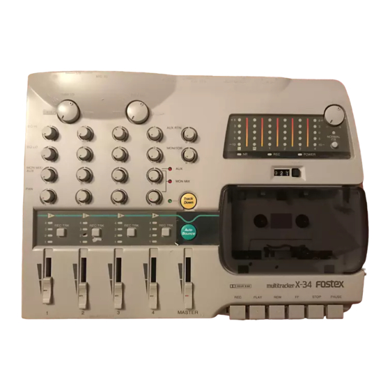
- Page 1 Service Manual Model multitracker...
-
Page 2: Safety Instructions
(including amplifiers) that produce heat. Power Sources - The appliance should be connected to a power supply only of the type described in the operating instructions or as marked on the appliance. Grounding or Polarization - The precautions that should be taken so that the grounding or polarization means of an appliance is not defeated. -
Page 3: Table Of Contents
NOTES Adjusting Procedures, Parts List and circuit diagrams are given in this manual to assist the service technician in maintaining the Model X-34. The following accessories are supplied with X-34 as the standard accessories. Owner's manual AC adaptor AD-12C Following is the packing material for the Model X-34. -
Page 4: Specifications
X-34 1. SPECIFICATIONS DEFINITION Specification Unit Normal Fader Position Input fader Condition Master fader Condition MIXER SECTION Standard Input MIC IN Connector Input level Impedance LINE IN / INSERT (RTN) Connector Input level Impedance AUX RTN L (MONO) / R... - Page 5 0 ± 7 (FF from BOT to EOT and then RWD to BOT again.) -10 ± 1 dB (TCW-231 test tape) -10 ± 1 dBV (AC-514 test tape) Test tape: SCW-977 / TCW-284F (NR: OUT) +3 dB -3 dB 40 Hz 400 Hz X-34 12.5 kHz...
- Page 6 X-34 RECORDER SECTION (continued) REC & PLAY Level Deviation at Ref. Output Level PLAY REC & PLAY PLAY REC & PLAY Distortion (with 400 Hz HPF & 30 kHz LPF) (REC & PLAY) Erasure Ratio Cross Erasure Channel Separation Sync Crosstalk...
-
Page 7: Controls, Indicators And Connectors
Play button [ PLAY ] Stop button [ STOP ] Fast forward button [ FF ] Rewind button [ REW ] Recording button [ REC ] Pause button [ PAUSE ] WIDE PITCH – NORMAL 18, 19, 20 POWER RESET X-34 STOP PAUSE X-34... -
Page 8: Adjusting Procedures
X-34 < Front Panel > 1. Line in / insert jacks jacks [ LINE IN/INSERT 1, 2, 3, 4 ] 2. Headphone jack [ PHONES ] < Rear Panel > 1. Mic inut jacks [ MIC IN 1/3, 2/4 ] 2. - Page 9 Demagnetizing Procedures After turning off the power of Model X-34, open the cassette lid and if a cassette tape is loaded, remove and place it far away from the deck. Switch on the head demagnetizer while holding it about one meter away from the Model X-34. Then, slowly move the head demagnetizer tip to the head and wave the tip up and down several times close to the head surface.
- Page 10 X-34 3-4. Tape Travel Check and Adjustment Using the mirror type cassette, check to see that the tape is running stable between the ERASE and REC/PLAY heads tape guides without weaving. If the tape is not running stable between the guides, erasure and frequency response will be affected or the tape will be damaged by curling.
- Page 11 Connect an AC volt meter to the TAPE OUT 1 ~ 4 pin jacks. The X-34 is in the Input Monitor mode. Adjust the Input Fader so that the level at TAPE OUT 1 ~ 4 is -10 dBV (0.3 V).
- Page 12 X-34 3-13. Overall Frequency Response Adjustment Set the controls under the same condition as 3.12 except the DOLBY switch. (The switch should be turned on.) Apply a 400 Hz, -35 dBV (18 mV) signal to the MIC/LINE IN 1/3 and 2/4 phone jacks.
- Page 13 Plug the foot switch (e.g. Model 8051) in the Punch in/out jack and press the REC & PLAY buttons. Press the foot switch repeatedly and check if the click level at TAPE OUT 1 ~ 4 is less than -20 dBV X-34...
-
Page 14: Exploded View, Pcb Assembly And Parts List
X-34 OVERALL EXPLODED VIEW & PARTS LIST Ref. No. Part No. 8212 6550 00 Case, bottom, X-34 8274 1610 00 PCB assy, R/P AMP, X-34 8216 6910 00 Shield, bottom, X-34 8204 0820 00 Plate, mounting, B 8270 8240 00 Transport assy, X-24/34... - Page 15 X-34 X-34 OVERALL EXPLODED VIEW Letter Size X 2...
- Page 16 X-34 X-34 TRANSPORT EXPLODED VIEW Letter Size X 2...
- Page 17 X-34 X-34 PCB PATTERN DRAWING • MIXER / METER / TERMINAL PCBs Letter Size X 2...
- Page 18 X-34 • R/P / PITCH / TRK SELECTOR PCBs Letter Size X 2...
- Page 19 U012, 013 8236 5412 00 ST, AN, NJM4565M U014 8236 5702 01 ST, DG, driver, DTC314TK U020 8236 0854 01 QFP, DG, CPU, X-34, TMP87C800 U021~037 8236 5707 01 ST, DG, driver, DTA144EK U038 8236 5706 01 ST, DG, driver, DTC144EK...
- Page 20 X-34 Ref. No. Part No. R162, 262 8230 5001 04 ST, carbon, 1/10W, 100k , 5% R163, 263 8230 5004 73 ST, carbon, 1/4W, 47k , 5% R164, 264 8230 1381 02 HT, carbon, 1/10W, 1k , 5% R165, 265 8230 1384 73 HT, carbon, 1/4W, 47k , 5%...
- Page 21 S001 8253 1350 02 Switch, PIT, tact, SOR-112HS • TRK SELECTOR PCB Ref. No. Part No. Description 8274 1780 00 PCB assy, Trk Selector, X-34 B001 8251 9711 03 Plain PCB, Trk Selector, X-34 Ref. No. Part No. Description U052~072 8236 5707 01 ST, DG, driver, DTA144EK...
- Page 22 8236 0352 03 SIP, AN, op amp, NJM4556AL U003 8236 0782 06 ST, digital, driver, DTA143TS U004 8236 0854 01 QFP, DG, CPU, X-34, TMP87C800 U005 8236 5701 03 ST, digital, driver, DTC114TK U006~034 8236 5707 01 ST, digital, driver, DTA144EK...
- Page 23 8207 0122 03 Holder, cable, 3P, 51048 J001 8245 5410 00 Connector, PL, jack, DC-inlet, YKB21-0012 J002 8245 3390 10 Connector, PL, jack, phone, YKB21-5078 J003 J004 8245 3080 09 Connector, PI, jack, SBRK9S-4 J005 8245 5470 09 Connector, PI, jack, PH, 9P, WHT X-34...
- Page 24 8245 5470 05 Connector, PI, jack, PH, 5P, WHT J201 8245 5471 05 Connector, PI, jack, PH, 5P, RED • TERMINAL PCB Ref. No. Part No. 8274 1950 00 PCB assy, Terminal, X-34 B001 8251 9750 04 Plain PCB, Terminal, X-34 Ref. No. Part No. E101...
-
Page 25: Circuit & Block Diagrams
X-34 5. CIRCUIT & BLOCK DIAGRAMS MIXER, X-34 Letter Size X 2... - Page 26 X-34 R/P, X-34 Letter Size X 2...
- Page 27 X-34 R/P CONTROL, X-34 Letter Size X 2...
- Page 28 X-34 CPU, MIX / BARGRAPH METER, X-34 Letter Size X 2...
- Page 29 REC SEL, X-34 A.B LED2 DTA144EK TRK LED2 DTA144EK TRK LED2 DTA144EK MC74HC137 TRK LED2 DTA144EK TRK LED1 DTA144EK REC SEL2 A.B LED1 DTA144EK TRK LED4 DTA144EK TRK LED3 DTA144EK MC74HC137 TRK LED2 DTA144EK TRK LED2 DTA144EK REC SEL1 T.D LED DTA114EK A.B LED...
- Page 30 X-34 TERMINAL, X-34 J001 SBK7S-4 J002 8283-14P 9073/BS FLAT/14P...
-
Page 31: Block Diagram
BLOCK DIAGRAM INPUT/PLAYBACK INPUT1 FADER 2BAND EQ INPUT1 TAPE1 AUTO BOUNCE INPUT/PLAYBACK INPUT2 FADER 2BAND EQ INPUT2 TAPE2 AUTO BOUNCE INPUT/PLAYBACK INPUT3 FADER 2BAND EQ INPUT3 TAPE3 AUTO BOUNCE INPUT/PLAYBACK INPUT4 FADER 2BAND EQ INPUT4 TAPE4 AUTO BOUNCE MIC/LINE INPUT STEREO RETURN L(MONO) - Page 32 FOSTEX CORPORATION 3-2-35 Musashino, Akishima, Tokyo, Japan 196-0021 FOSTEX CORPORATION OF AMERICA 15431 Blackburn Ave., Norwalk, CA 90650, U.S.A. © PRINTED IN JAPAN FEB. 1999 8288781000...
Need help?
Do you have a question about the X-34 and is the answer not in the manual?
Questions and answers