Table of Contents
Advertisement
Quick Links
Germany | Switzerland | Austria
Benelux
Althen GmbH Mess- & Sensortechnik
Althen bv Sensors & Controls
Tel: + 49 (0)6195 - 70060
Tel: +31 (0)70 392 4421
info@althen.de
sales@altheris.nl
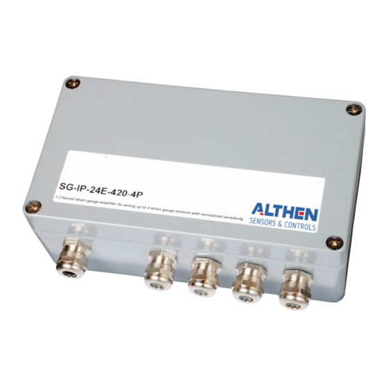
Single Channel Strain Gauge Amplifier
for up to 4 parallel normalized sensors
SG-IP-12E/24E-xxx-4P
France
Althen / DB Innovation
Tél : 0033 (0)4 67 78 61 66
info@althensensors.fr
Sweden
USA | Canada
Althen Sensors & Control AB
Altheris Inc Sensors & Controls Inc.
Tel. +46 (0)8 7 95 24 90
Tel: +1 858-633-3572
info@althensensors.de
info@althensensors.com
Other Countries
please contact us
by email at
sales@althensensors.com
www.althen.de
V2.1 eng
Advertisement
Table of Contents

Related Manuals for ALTHEN SG-IP-12E 4P Series


Summary of Contents for ALTHEN SG-IP-12E 4P Series
- Page 1 Germany | Switzerland | Austria Benelux France Sweden USA | Canada Other Countries Althen GmbH Mess- & Sensortechnik Althen bv Sensors & Controls Althen / DB Innovation Althen Sensors & Control AB Altheris Inc Sensors & Controls Inc. please contact us...
-
Page 2: Table Of Contents
Content 1 General Information ..........................3 1.1 Safety Instructions ..........................3 1.2 Qualified Personnel ..........................3 1.3 Intended Use ............................3 2 Instructions for use of the measuring amplifier ................4 2.1 Instructions for use of strain gauge sensors ................. 5 3 Technical description ..........................5 4 Terminal assignment .......................... -
Page 3: General Information
1.3 Intended Use Amplifiers from Althen Mess- & Sensortechnik GmbH serve to measure the intended measurand and the evaluation thereof in combination with one or more sensors. Any other use over and above that is regarded as non-intended use. -
Page 4: Instructions For Use Of The Measuring Amplifier
Notice: Changes of the amplifier of any kind demands for the explicit approval of Althen Mess- & Sensortechnik GmbH. Changes of any kind done without that approval exclude all possible warranty and/or liability of Althen Mess- & Sensortechnik GmbH. -
Page 5: Instructions For Use Of Strain Gauge Sensors
2.1 Instructions for use of strain gauge sensors Notice: Strain gauge sensors with a small range are extremely sensitive to improper handling. Force transducers can be destroyed simply by touching. Same applies for the diaphragms of pressure transducers. So, bear in mind: handle with care! Loading the transducer in excess of the nominal range may result in an increased and lasting zero balance offset as well as damage to the sensor. -
Page 6: Terminal Assignment
4 Terminal assignment The electrical connections are made via cable glands to terminal blocks inside. The terminal numbering can be found on the pcb. The maximum cable cross-section is 2,5 mm². The EMC-installation instruction must be complied with. Notice: The amplifier must be operated with closed lid only. Clamp Description Clamp... -
Page 7: Galvanic Isolation
4.1.1 Galvanic isolation The supply voltage of the amplifier is galvanically isolated from analogue output, sensor supply and sensor signal. To unset this isolation, clamp 2(3) and 4 have to be bridged. 4.2 Strain gauge excitation voltage The transducer can be supplied with either 10 VDC or 5 VDC unipolar voltage. This value can be selected with solder points (LP-04 and LP-05) for coarse, and with potentiometers (P-03 and P-04) for fine adjustment. -
Page 8: Analogue Output
4.3 Analogue output The following standardized analogue outputs, depending on the ordered option, are available: Version …010: The output is: 0 … +10 Volts (max 1 mA) Version …B10: The output is: ± 10 Volts (max 1 mA) Version …420: The output is: 4 …... -
Page 9: Setpoints (Option Gw)
The setpoints can be set freely over the complete range of the measurement by using the potentiometers P-100 and P-101 on the additional pcb (Althen 112). The adjustment may be executed either with loaded sensor(-s), or by measuring the desired voltage on the pcb (Althen 112) on the measuring points (GW- MP.1/2). -
Page 10: Starting Up
The test-signals are scaled as follows: threshold (phys. unit)x 10 V GW-test signal (Volt) measuring range (phys. unit) Notice: After adjusting the setpoints the potentiometers are to be sealed with anti-temper seal/ protective coating. 5 Starting up If an adjustment (A-K-1K / A-D-1K) has been ordered in combination with the amplifier(-s) and/or transducers(-s) it may be necessary for a slight fine adjustment nonetheless. -
Page 11: Zero Point Adjustment Range
5.1 Zero point adjustment range It is to be noted that there is a slight dependence between zero-point adjustment and amplification (gain). The zero-point adjustment range is approx. ± 10 %. This range can be changed by setting the dip-switch according to the table below: Fig. -
Page 12: Tare
5.1.1 Tare A potential base load can be electrically suppressed by an additional resistor (-network) on the pcb, if an expansion of the zero-point adjustment range is neither sufficient, nor desirable. In order to do so, a combination of resistors, respectively bridges and one potentiometer has to be soldered in. - Page 13 Notice: A base load reduces the remaining load capacity by just that value. Overloading may cause damage! 5.2 Adjustment / calibration of the amplifier In order to adjust or calibrate the amplifier at least one multimeter has to be connected to one of the analogue outputs.
-
Page 14: Correction Of The Analogue Current Output
5.2.1 Correction of the analogue current output The minimum of analogue current output is 4 mA. A lower P-06 current is not possible. When calibrating, the zero-point ZERO Output current has to be set to 4,1 mA with the potentiometer P- 06. -
Page 15: Maintenance
According to European and German law, it is prohibited to dispose of old electronic devices by household waste, but must be collected and disposed of separately. Amplifiers and measurement units manufactured and sold by Althen Mess- & Sensortechnik GmbH serve B2B purposes only. Therefore, those old appliances must not be given to the communal disposer, but must be given back to the seller or disposed of properly. -
Page 16: Appendix
Appendix Datasheet (full bridge resistance > 300 Ω), parallel operating Number of measuring channels: of up to 4 transducers with normalized signal 10…18 VDC Supply voltage: Electronic protected against voltage reversal 18…30 VDC Isolating proof voltage input to output: 200 V Higher isolated proof voltage on request Power consumption: max. -
Page 17: Component Diagram
Component diagram 17 | 18... -
Page 18: Housing Dimensions
Housing dimensions Subject to modifications. All information describes our products in general form. 18 | 18...
Need help?
Do you have a question about the SG-IP-12E 4P Series and is the answer not in the manual?
Questions and answers