Table of Contents
Advertisement
Germany | Switzerland | Austria
Benelux
Althen GmbH Mess- & Sensortechnik
Althen bv Sensors & Controls
Tel: + 49 (0)6195 - 70060
Tel: +31 (0)70 392 4421
info@althen.de
sales@altheris.nl
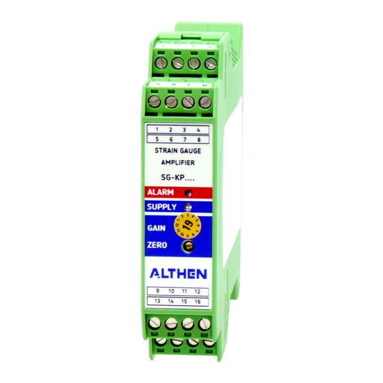
Single Channel Strain Gauge Amplifier
SG-KP-12E/24E-xxx
France
Althen / DB Innovation
Tél : 0033 (0)4 67 78 61 66
info@althensensors.fr
Sweden
USA | Canada
Althen Sensors & Control AB
Altheris Inc Sensors & Controls Inc.
Tel. +46 (0)8 7 95 24 90
Tel: +1 858-633-3572
info@althensensors.de
info@althensensors.com
Other Countries
please contact us
by email at
sales@althensensors.com
www.althen.de
V2.1 eng
Advertisement
Table of Contents

Related Manuals for ALTHEN SG-KP Series


Summary of Contents for ALTHEN SG-KP Series
- Page 1 Germany | Switzerland | Austria Benelux France Sweden USA | Canada Other Countries Althen GmbH Mess- & Sensortechnik Althen bv Sensors & Controls Althen / DB Innovation Althen Sensors & Control AB Altheris Inc Sensors & Controls Inc. please contact us...
-
Page 2: Table Of Contents
Content 1 General Information 1.1 Safety Instructions 1.2 Qualified Personnel 1.3 Intended Use 2 Instructions for use of the measuring amplifier 2.1 Instructions for use of strain gauge sensors 3 Technical description 4 Terminal Assignment 4.1 Supply voltage 4.1.1 Galvanic isolation 4.2 Strain gauge excitation voltage 4.2.1 Connecting in 4 or 6 wire technology 4.2.2 Connecting in 4 wire technology... -
Page 3: General Information
To ensure reliable and safe operation, the measuring amplifier must be operated in compliance with the specifications according to this technical description only. These regulations must also be observed if using accessories, that have been ordered from Althen Mess- & Sensortechnik GmbH together with the measuring amplifier. -
Page 4: Instructions For Use Of The Measuring Amplifier
The amplifier must be operated with a separate power source used for measurement devices only. Notice: Changes of the amplifier of any kind demand for the explicit approval of Althen Mess- & Sensortechnik GmbH. Changes of any kind done without that approval exclude all possible warranty and/or liability of Althen Mess- &... -
Page 5: Instructions For Use Of Strain Gauge Sensors
2.1 Instructions for use of strain gauge sensors Notice: Strain gauge sensors with a small range are extremely sensitive to improper handling. Force transducers can be destroyed simply by touching. Same applies to the diaphragms of pressure transducers. So, bear in mind: handle with care! Loading the transducer in excess of the nominal range may result in an increased and lasting zero balance offset as well as damage to the sensor. -
Page 6: Terminal Assignment
4 Terminal Assignment The electrical connections are made via screw-clamps. The numbering can be found on the front side of the clamps. The maximum wire cross section is 2,5 mm². The EMC-installation instruction is to be complied with. Maximum interference immunity is achieved by direct connection of the cable screen with “clean”... -
Page 7: Supply Voltage
4.1 Supply voltage The supply voltage of version -24E is in the range of 18 to 30 VDC and version –E12 within 10 to 18 VDC. The presence of the supply / internal operating voltage is indicated by the 2 green LEDs on the front. -
Page 8: Connecting In 4 Or 6 Wire Technology
4.2.1 Connecting in 4 or 6 wire technology The described measuring amplifier allows to connect the transducer in either 4 or 6 wire technology. The excitation voltage received by the sensor has great influence on the sensors signal. So, if with a very long cable, or lengthening of it, the excitation voltage drops even by a slight value the signal drops accordingly. -
Page 9: Lenghening A Cable In 4 Wire Technology
4.2.3 Lenghening a cable in 4 wire technology As mentioned above the connection should be in 6 wire technology if the sensor comes with no hard- mounted cable or the existing cable is to be lengthened. Example: The sensor has been calibrated with an excitation of 10,000 V. Transducer cable Cable lengthening +SG-Excitation... -
Page 10: Connecting In 6 Wire Technology
4.2.4 Connecting in 6 wire technology Notice: When connecting in 6 wire technology the jumpers J1 and J2 must be removed. Otherwise the 6-wire technology does not have the desired effect. Transducer cable +SG-Excitation +Sense SG-Amplifier wire=0,5 Ohm 350 Ohm wire=0,5 Ohm -Sense -SG-Excitation... -
Page 11: Analogue Output Voltage
4.3.1 Analogue output voltage The analogue voltage output can be picked up on the corresponding clamps. See chapter 4 “Terminal Assignment”. In combination with a transducer which is capable to handle tension and compression forces an analogue output of ± 10 volts is available. If an unipolar voltage is needed with such a sensor it is possible to set the zero point of the transducer to 5 volts of the output. -
Page 12: Startign Up
5 Starting up If an adjustment (A-K-1K / A-D-1K) has been ordered in combination with the amplifier(-s) and/or transducers(-s) it may be necessary for a slight fine adjustment nonetheless. This is due to possible various environmental influences as well as to mounting etc. If any visual damage or malfunctions are noticed, the measuring system must be switched off and marked appropriately. -
Page 13: Adjustment / Calibration Of The Amplifier
5.2 Adjustment / calibration of the amplifier In order to adjust or calibrate the amplifier a multimeter has to be connected to the analogue output. Inspection: Unload the measuring device. ■ Connect the multimeter (refer to chapter 4 “Terminal Assignment”). ■... -
Page 14: Correction Of The Analogue Current Output
5.2.1 Correction of the analogue current output The minimum of analogue current output is 4 mA. A lower current is not possible. When calibrating, the zero-point current has to be set to 4,1 mA with the potentiometer “NULLPUNKT”. Now the range of the current output can be set to 16 mA by using the potentiometer P-03. -
Page 15: Maintenence
Amplifiers and measurement units manufactured and sold by Althen Mess- & Sensortechnik GmbH serve B2B purposes only. Therefore, those old appliances must not be given to the communal disposer, but must be given back to the seller or disposed of properly. -
Page 16: Appendix
Appendix Datasheet Number of measuring channels: 1 (Strain gauge full bridge > 300 Ω) 12E - 10 … 18 VDC Supply voltage: Electronics protected against voltage reversal 24E - 18 … 30 VDC Isolating proof voltage input to output: 200 V Higher isolated proof voltage on request Power consumption: max. -
Page 17: Component Diagram
Component diagram DIP-50 Zero Point - Range DIP-60 1+2: Increase Signal 3+4: Low-pass-filter (R3); Visible after removing the EMC-plate LP81-1 SG-Exc. voltage LP81-2 SG-Exc. voltage 17 | 18... -
Page 18: Housing Dimensions
Housing dimensions Subject to modifications. All information describes our products in general form. 18 | 18...
Need help?
Do you have a question about the SG-KP Series and is the answer not in the manual?
Questions and answers