Table of Contents
Advertisement
Available languages
Available languages
Quick Links
Advertisement
Chapters
Table of Contents

Related Manuals for Carel SmartCella 3PH Series


Summary of Contents for Carel SmartCella 3PH Series
- Page 1 SmartCella 3PH Controllo elettronico per celle frigorifere trifase Electrical controller for three-phase cold rooms Guida rapida Quick guide NO POWER & SIGNAL CABLES TOGETHER READ CAREFULLY IN THE TEXT! H i g h E f f i c i e n c y S o l u t i o n s...
- Page 3 CAREL o le sue fi liali/affi liate siano state avvisate della possibilità di danni.
-
Page 5: Table Of Contents
Indice 1. CARATTERISTICHE GENERALI Descrizione ........................7 Istruzioni ed avvertenze generali ..............7 Codici ..........................7 Dimensioni ........................7 Planimetrie e componenti ...................8 Dati tecnici generali ....................8 Caratteristiche tecniche ..................9 Codici opzioni ......................9 Montaggio e collegamenti .................9 2. SCHEMI ELETTRICI Circuito di potenza ....................10 Circuito ausiliario ....................12 Morsettiera .........................14 Collegamenti per funzionamento con pump down... -
Page 7: Caratteristiche Generali
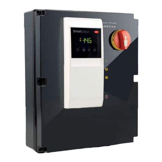
1. CARATTERISTICHE GENERALI 1.1 Descrizione 1.3 Codici Codice Descrizione Smartcella 3PH è una famiglia di quadri elettronici per la gestione di celle WP00B14A10 SmartCella 3PH 5.5HP salvamotore 1,6-2,5A sbrinamento frigorifere con carichi trifase. Includono al loro interno la stessa logica 3PH 6kW ventole evaporatore 1PH 500W ventole di controllo dei quadri Smartcella standard e gli attuatori di potenza condensatore 1PH 800W luce 1ph 800W... -
Page 8: Planimetrie E Componenti
1.5 Planimetrie e componenti Sigla Descrizione Smartcella Per codici WP00B34A10, WP00B24A10, WP00B14A10 Luce presenza tensione Luce evaporatore Luce compressore Luce allarme Luce sbrinamento Contattore ventola evaporatore Contattore compressore Contattore resistenze sbrinamento Relè allarme Magnetotermico ventola evaporatore/condensatore/resistenze sbrinamento Magnetotermico ausiliario Salvamotore compressore Sezionatore generale Morsettiera ausiliaria Morsettiera potenza... -
Page 9: Caratteristiche Tecniche
1.7 Caratteristiche tecniche Specifi che WP00B14A10 WP00B24A10 WP00B34A10 WP00B44A10 WP00B47B20 WP00B57B20 Alimentazione 400V 3~ +N+T 50/60Hz Potenza max compressore 5,5HP 7,5HP Protezioni Manovra Sezionatore Protezione eveporatore, Magneto- condensatore e termico sbrinamento Protezione compressore Salvamotore 1,6-2,5A 2,5-4A 4-6,3A 6,3-10A 10-16A regolabile Protezione circuito Magneto- ausiliario... -
Page 10: Schemi Elettrici
2. SCHEMI ELETTRICI 2.1 Circuito di potenza 2.1.1 Codici WP00B44A10, WP00B34A10, WP00B24A10, WP00B14A10 Fig. 2.a “SmartCella 3PH” +0500119IE - rel. 1.2 - 10.03.2017... - Page 11 2.1.2 Codici WP00B57B20, WP00B47B20 Fig. 2.b “SmartCella 3PH” +0500119IE - rel. 1.2 - 10.03.2017...
-
Page 12: Circuito Ausiliario
2.2 Circuito ausiliario Fig. 2.c “SmartCella 3PH” +0500119IE - rel. 1.2 - 10.03.2017... - Page 13 Fig. 2.d “SmartCella 3PH” +0500119IE - rel. 1.2 - 10.03.2017...
-
Page 14: Morsettiera
2.3 Morsettiera 2.3.1 Codici WP00B44A10, WP00B34A10, WP00B24A10, WP00B14A10 Morsettiera XP1 Morsettiera XA1 Fig. 2.e Morsettiera Numero Descrizione Tipo Morsettiera Numero Descrizione Tipo Ventilatore evaporatore Uscita Pressostato LP Ingresso Ventilatore condensatore Uscita Valvola solenoide Uscita Termico ventilatore Ingresso Resistenze sbrinamento Uscita Termostato di sicurezza Ingresso Resistenza carter... - Page 15 2.3.2 Codici WP00B57B20, WP00B47B20 Morsettiera XP1 Morsettiera XA1 Fig. 2.f Morsettiera Numero Descrizione Tipo Morsettiera Numero Descrizione Tipo Pressostato LP Ingresso Ventilatore evaporatore Uscita Valvola Uscita Ventilatore condensatore Uscita Termico ventilatore Ingresso Resistenze sbrinamento Uscita Termostato di sicurezza Ingresso Luci interne Uscita Resistenza carter Uscita...
-
Page 16: Collegamenti Per Funzionamento Con Pump Down Gestito Da Smartcella
2.4.2 Connessioni per pump down in pressione 2.4 Collegamenti per funzionamento con con avviamento simultaneo di compressore e pump down gestito da Smartcella valvola solenoide Nel caso in cui sia necessario eseguire il pump down comandato in 2.4.1 Connessioni per pump down in pressione con pressione, con avviamento e spegnimento simultaneo di compressore e spegnimento compressore in bassa pressione valvola solenoide, eseguire le connessioni secondo lo schema seguente... - Page 17 2.4.3 Connessioni per avviamento simultaneo di 2.4.4 Connessioni per pump down a tempo compressore e valvola solenoide Nel caso in cui sia necessario avere un avviamento e spegnimento della valvola solenoide a tempo, senza pressostato, eseguire le connessioni Nel caso sia necessario avere un avviamento e spegnimento simultaneo secondo lo schema seguente di compressore e valvola solenoide, senza pressostato, eseguire le connessioni secondo lo schema seguente...
-
Page 18: Interfaccia Utente
3. INTERFACCIA UTENTE 3.1 Display Segnalazioni sul display Icona Funzione Normale funzionamento Accensione Lampeggiante / blink COMPRESSORE compressore acceso compressore spento compressore richiesto VENTILATORE ventilatore acceso ventilatore spento ventilatore richiesto SBRINAMENTO sbrinamento in atto sbrinamento non richiesto sbrinamento richiesto uscita ausiliaria AUX attiva uscita ausiliaria AUX non attiva funzione anti-sweat heater attiva... -
Page 19: Tabella Parametri
4. TABELLA PARAMETRI Simbolo Codice Parametro U.M. Tipo Min. Max. Def. Password Stabilità misura sonde Mitigazione visualizzazione sonda Composizione sonda virtuale Unità di misura temperatura (0: °C ,1: °F) fl ag Visualizzazione punto decimale fl ag 0: con decimo di grado 1: senza decimo di grado Visualizzazione su terminale utente 1: sonda virtuale... - Page 20 Simbolo Codice Parametro U.M. Tipo Min. Max. Def. Tipo di sbrinamento fl ag 0: a resistenza in temperatura 1: a gas caldo in temperatura 2: a resistenza a tempo (Ed1, Ed2 non compaiono) 3: a gas caldo a tempo (Ed1, Ed2 non compaiono) 4: termostato a resistenza a tempo (Ed1, Ed2 non compaiono) Intervallo massimo tra sbrinamenti consecutivi 0= sbrinamento non eseguito...
- Page 21 Simbolo Codice Parametro U.M. Tipo Min. Max. Def. Gestione ventilatori fl ag 0: sempre accesi 1: attivazione in base a Sd-Sv (diff erenza tra la sonda virtuale e temperatura evaporatore) 2: attivazione in base a Sd (temperatura evaporatore) Temperatura attivazione ventilatori (solo con F0=1 o 2) °C/°F Ventilatori evaporatore con compressore spento fl...
-
Page 22: Segnalazione Allarmi
Note: Il buzzer viene attivato se abilitato dal parametro ‘H4’ . 6. FUNZIONI E REGOLAZIONI Per una descrizione dettagliata delle funzioni e regolazioni di SmartCella 3PH fare riferimento al manuale codice +0300084IT della gamma Smartcella, scaricabile dal sito www.carel.com. “SmartCella 3PH” +0500119IE - rel. 1.2 - 10.03.2017... - Page 23 The technical specifi cations shown in the manual may be changed without prior warning. The liability of CAREL in relation to its products is specifi ed in the CAREL general contract conditions, available on the website www.CAREL.com and/or by specifi c agreements with customers;...
- Page 25 Content 1. GENERAL FEATURES Description ........................7 General instructions and warnings ...............7 Part numbers .......................7 Dimensions ........................7 Layouts and components ..................8 General technical characteristics ..............8 Technical specifi cations ..................9 Option part numbers ....................9 Assembly and connections.................9 2. WIRING DIAGRAMS Power circuit ......................10 Auxiliary circuit ......................12 Terminal block ......................14 Connections for pump down operation managed...
-
Page 27: General Features
1. GENERAL FEATURES 1.1 Description 1.3 Part numbers Description Smartcella 3PH is a family of electronic control panels for the management WP00B14A10 SmartCella 3PH 5.5HP 1.6-2.5A motor protector 3PH 6kW of cold rooms with three-phase loads. These feature the same control defrost 1PH 500W evaporator fans 1PH 800W condenser logic as the standard Smartcella panels, plus power actuators to directly fans 1PH 800W light... -
Page 28: Layouts And Components
1.5 Layouts and components Code Description Smartcella For part numbers WP00B34A10, WP00B24A10, Power light Evaporator light WP00B14A10 Compressor light Alarm light Defrost light Evaporator fan contactor Compressor contactor Defrost heater contactor Alarm relay Evaporator/condenser fan/defrost heater circuit breaker Auxiliary circuit breaker Compressor motor protector Main disconnect switch Auxiliary terminal block... -
Page 29: Technical Specifi Cations
1.7 Technical specifi cations Specifi cations WP00B14A10 WP00B24A10 WP00B34A10 WP00B44A10 WP00B47B20 WP00B57B20 Power supply 400V 3~ +N+E 50/60Hz Max compressor power 5.5HP 7.5HP Protectors Power Disconnect switch Evaporator, condenser and Circuit defrost protection breaker Compressor protection Adjustable motor 1.6-2.5A 2.5-4A 4-6.3A 6.3-10A 10-16A... -
Page 30: Wiring Diagrams
2. WIRING DIAGRAMS 2.1 Power circuit 2.1.1 Part numbers WP00B44A10, WP00B34A10, WP00B24A10, WP00B14A10 Fig. 2.a “SmartCella 3PH” +0500119IE - rel. 1.2 - 10.03.2017... - Page 31 2.1.2 Part numbers WP00B57B20, WP00B47B20 Fig. 2.b “SmartCella 3PH” +0500119IE - rel. 1.2 - 10.03.2017...
-
Page 32: Auxiliary Circuit
2.2 Auxiliary circuit Fig. 2.c “SmartCella 3PH” +0500119IE - rel. 1.2 - 10.03.2017... - Page 33 Fig. 2.d “SmartCella 3PH” +0500119IE - rel. 1.2 - 10.03.2017...
-
Page 34: Terminal Block
2.3 Terminal block 2.3.1 Part numbers WP00B44A10, WP00B34A10, WP00B24A10, WP00B14A10 Terminal block XP1 Terminal block XA1 Fig. 2.e Terminal block Number Description Type Terminal block Number Description Type Evaporator fan Output LP pressure switch Input Condenser fan Output Solenoid valve Output Fan thermal protector Input... - Page 35 2.3.2 Part numbers WP00B57B20, WP00B47B20 Terminal block XP1 Terminal block XA1 Fig. 2.f Terminal block Number Description Type Terminal block Number Description Type LP pressure switch Input Evaporator fan Output Valve Output Condenser fan Output Fan thermal protector Input Defrost heaters Output Safety thermostat Input...
-
Page 36: Connections For Pump Down Operation Managed By Smartcella
2.4.2 Connections for pump down by pressure with 2.4 Connections for pump down operation simultaneous compressor and solenoid valve managed by Smartcella activation If pump down is controlled based on pressure, with simultaneous 2.4.1 Connections for pump down by pressure with compressor and solenoid valve activation, the connections are as shown compressor shutdown due to low pressure in the following diagram... - Page 37 2.4.3 Connections for simultaneous compressor and 2.4.4 Connections for pump down by time solenoid valve activation If solenoid valve needs to be activated and deactivated by time, without using a pressure switch, the connections are as shown in the following If shutdown simultaneous compressor and solenoid valve activation diagram and deactivation are required, without using a pressure switch, the...
-
Page 38: User Interface
3. USER INTERFACE 3.1 Display Signals on the display Icon Function Normal operation Start-up Blink COMPRESSOR compressor on compressor off compressor call fan on fan off fan call DEFROST defrost in progress defrost not required defrost call AUX output active AUX output not active anti-sweat heater function active ALARM... -
Page 39: Parameter Table
4. PARAMETER TABLE Symbol Code Parameter Type Min. Max. Def. Password Probe measurement stability Probe display stability Virtual probe composition Temperature unit of measure (0: °C .1: °F) fl ag Display decimal point fl ag 0: with tenths of a degree 1: without tenths of a degree Display on user terminal 1: virtual probe... - Page 40 Symbol Code Parameter Type Min. Max. Def. Type of defrost fl ag 0: heater by temperature 1: hot gas by temperature 2: heater by time (Ed1, Ed2 not shown) 3: hot gas by time (Ed1, Ed2 not shown) 4: heater with thermostat by time (Ed1, Ed2 not shown) Maximum time between consecutive defrosts 0= defrost not performed End defrost temperature probe 2...
- Page 41 Symbol Code Parameter Type Min. Max. Def. Fan management fl ag 0: always on 1: activation based on Sd-Sv (diff erence between virtual probe and evaporator temperature) 2: activation based on Sd (evaporator temperature) Fan activation temperature (only with F0=1 or 2) °C/°F Evaporator fans with compressor off...
-
Page 42: Alarm Signals
Note: the buzzer is activated if enabled by parameter ‘H4’ . 6. FUNCTIONS AND CONTROL For a detailed description of the functions and control logic of SmartCella 3PH, see manual +0300084EN pertaining to the Smartcella range, downloadable from www.carel.com. “SmartCella 3PH” +0500119IE - rel. 1.2 - 10.03.2017... - Page 44 Agenzia / Agency: CAREL INDUSTRIES S.p.A. Via dell’Industria, 11 - 35020 Brugine - Padova (Italy) Tel. (+39) 049.9716611 - Fax (+39) 049.9716600 e-mail: carel@carel.com - www.carel.com...
Need help?
Do you have a question about the SmartCella 3PH Series and is the answer not in the manual?
Questions and answers