3M PX5 Series Reference Manual
Multi-touch asic controller
Hide thumbs
Also See for PX5 Series:
- User manual (95 pages) ,
- Reference manual (34 pages) ,
- Safety manual (22 pages)
Table of Contents
Advertisement
3M
Multi-Touch
™
ASIC Controller PX5nnn
Reference Guide
PX5210, PX5218, PX521A, PX521C, PX521E,
PX521X, PX521Y, PX521Z, PX5318, PX531A,
PX531Z, PX5410, PX5515, PX5516, PX5517
Please read, understand and follow all safety information
contained in the 3M™ Multi-Touch PCT System Integration Guide
found at 3M.com/Touch prior to the use of this device.
Retain the Integration Guide for future reference.
3M Touch Systems, Inc. Proprietary Information
Advertisement
Table of Contents

Related Manuals for 3M PX5 Series


Summary of Contents for 3M PX5 Series
- Page 1 PX531Z, PX5410, PX5515, PX5516, PX5517 Please read, understand and follow all safety information contained in the 3M™ Multi-Touch PCT System Integration Guide found at 3M.com/Touch prior to the use of this device. Retain the Integration Guide for future reference. ...
- Page 2 3M Touch Systems, Inc. warranty, then 3M Touch Systems, Inc. sole obligation and User’s and Purchaser’s exclusive remedy, will be, at 3M Touch Systems, Inc. option, to repair or replace that Product quantity or software media or to refund its purchase price.
-
Page 3: Table Of Contents
3M Touch Systems Support Services ................ 6 Contact 3M Touch Systems ..................6 Chapter 2 Integrating the 3M™ Multi-Touch Controller PX5nnn Overview of the 3M PX5nnn Controllers ..............7 Handling and ESD Protection ................... 8 Establishing the Data Connection ................8 Sensor Connection ..................... 8 Supplying Power to the Controller ................ -
Page 4: Introduction
3M™ Multi-Touch ASIC Controller Reference Guide CHAPTER 1 Introduction 3M Touch Systems offers several multi-touch controllers designed for reliability and easy installation. Each controller provides superior performance and delivers excellent stability, sensitivity, accuracy, and fast response. These controllers are available to work with sensors ranging from 7 inches to 65 inches. -
Page 5: What You Need To Know
3M Touch Systems is committed to being a premier supplier in touch systems throughout the world. As a 3M Touch Systems customer, you are aware that we have strong internal programs that meet or exceed environmental regulations of our customers and the regions in which we conduct business. -
Page 6: 3M Touch Systems Support Services
5:30 p.m. until 8:00 p.m. US Eastern Standard Time – 9 a.m. to 5 p.m. throughout Europe. You can contact 3M Touch Systems Technical Support (US only – Eastern Standard Time) by calling the hot line, sending email or a fax. -
Page 7: Integrating The 3M™ Multi-Touch Controller Px5Nnn
Power requirements and options Overview of the 3M PX5nnn Controllers The 3M PX5nnn controller has a built-in Universal Serial Bus (USB) full speed interface. A full speed USB interface has a data rate of 12 Mb/s. To integrate and test the 3M PX5nnn controller, you need the following items: •... -
Page 8: Handling And Esd Protection
Establishing the Data Connection USB Connection In USB mode, the controller uses a 3M Touch Systems USB communication cable (P/N 7319420) PC 99 compatible or equivalent interconnects. One end of this cable plugs into the USB connector on the PX5000 series controller. The other end has a Type-A connector, and plugs into a USB port on your PC. -
Page 9: Supplying Power To The Controller
3M™ Multi-Touch ASIC Controller Reference Guide Take the tail straight from the sensor and carefully align with the ZIF connector. Connector Locking Styles Controllers may be built using one or more of the three Connector Locking Stytles shown below. Mounting the Controller The controller should be mounted internally and positioned to mate with the sensor flex tails without placing strain on the connections. -
Page 10: Mounting The Sensor
Mounting the Sensor There are several methods for mounting the sensor depending on your application. If you need instructions or recommendations from 3M Touch Systems on how to incorporate a sensor into your design, refer to the 3M Multi-Touch PCT System Integration Guide (TSD-48194). -
Page 11: Video Alignment
3M™ Multi-Touch ASIC Controller Reference Guide Video Alignment The 3M Multi-Touch PCT PX Series System does not require video alignment if you are able to accurately touch icons on the sensor. If after integrating the system you cannot do this, the touch sensor’s active area may not be correctly aligned to the underlying video. - Page 12 3M™ Multi-Touch ASIC Controller Reference Guide 2. If you are using 3M™ MicroTouch™ MT 7 Software, launch the MT 7 Control Panel and follow the instructions on the Main tab. You'll be asked to touch 3 targets. 3. If you are writing your own drivers, you should provide your own video alignment tool.
-
Page 13: 3M™ Px5Nnn Controller Communications
You should be aware of the results before executing any firmware commands. To optimize the performance of the PX5nnn controller and simplify the development of custom drivers, 3M Touch Systems recommends you use the commands listed in this chapter for current development. Communication Basics This section provides information on sending firmware commands to the controller and interpreting the responses that the controller returns. -
Page 14: Receiving Reports From The Controller
3M™ Multi-Touch ASIC Controller Reference Guide The computer can also send requests to the controller to change how it operates or receives information about the controller. The controller issues a synchronous report in response to some of these requests. You need to know product ID and the vendor ID to write your own driver. These values are required for identifying the controller and can be found in spec # TSD-48146. - Page 15 3M™ Multi-Touch ASIC Controller Reference Guide Table 7. Calibration Data Stage Offset Field Size Value Description Report ID 0x03 Feature report ID Report Subtype 0x04 Indicates a calibration request bCalType 0xXX 0x01 = Extended cal (CX) Not used Not used The device stalls endpoint 0 if the command cannot be processed successfully.
-
Page 16: Get Feature - Get Status
3M™ Multi-Touch ASIC Controller Reference Guide (0, 0) [0, 0] 1679, 0) [32767, 0] Upper Right Calibration Target (1439, 135) X = 1679 – (1920 x 1/8) = 1679 – 240 = 1439 Y = 0 + (1080 x 1/8) = 0 + 135 = 135... -
Page 17: Get Feature - Get Max Count
3M™ Multi-Touch ASIC Controller Reference Guide Table 11. Power On Check Bit Fields Bit Number Description Notes Not used ROM_ERROR Code area checksum error PWM Error Touch screen not connected or potential problem. NOV_ERROR Parameter Block1 checksum error HDW_ERROR Problem with ADCs... -
Page 18: Set Feature - Reset
3M™ Multi-Touch ASIC Controller Reference Guide Table 14. Get Max Count Data Stage Offset Field Size Value Description Report ID 0x12 Feature Report ID Max Count 0xNN Number of actual fingers supported (NN= maximum number of “Actual Counts” in the touch report) Set Feature –... -
Page 19: Set Feature - Restore Defaults
3M™ Multi-Touch ASIC Controller Reference Guide Set Feature – Restore Defaults This is a request to restore parameter defaults. If you did not connect the sensors tails correctly, you may not get the full advantage of your touch screen size. Typically, on initial power-up, the controller will automatically detect the correct size of the touch sensor. - Page 20 3M™ Multi-Touch ASIC Controller Reference Guide Table 19. Get Controller ID Setup Stage Offset Field Size Value Description bmRequestType 0xA1 Class,D2H,Interface bRequest 0x01 Get Report wValue 0x0304 msb=03=Feature lsb=04= Feature Report ID wIndex 0x0000 Always 0 wLength 0x0018 Always 24 Table 20.
-
Page 21: Asynchronous Reports
3M™ Multi-Touch ASIC Controller Reference Guide Asynchronous Reports Depending on the firmware, one of these two reports will be sent when using this feature. These are used to transfer the coordinate data to the host. One of these reports, depending of the particular firmware used, is sent to the host whenever new data is available or scheduled for transmission. -
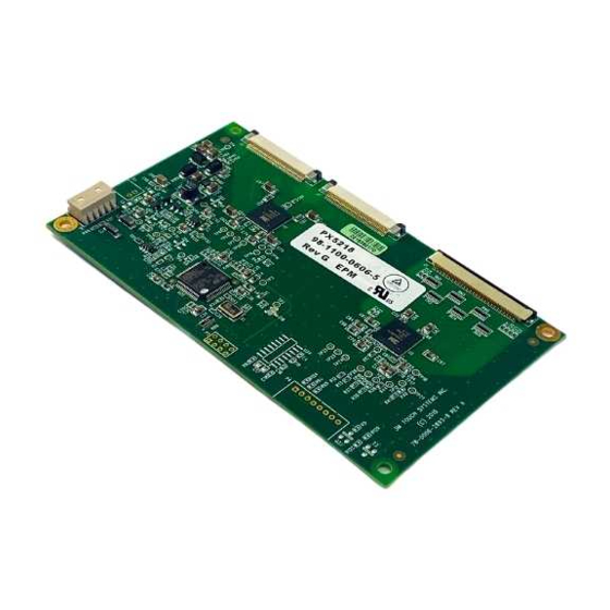
Page 22: Controller Drawings
Touch ID 0-255 Touch thread ID number X lsb 0xXX X ( 0-7FFF) X msb 0xXX Y lsb 0xXX Y ( 0-7FFF) Y msb 0xXX Controller Drawings Request drawings from your 3M Touch Systems representative. 3M Touch Systems, Inc. Proprietary Information...
Need help?
Do you have a question about the PX5 Series and is the answer not in the manual?
Questions and answers