
Subscribe to Our Youtube Channel
Related Manuals for DINSE DIX PI GO 1156.M


Summary of Contents for DINSE DIX PI GO 1156.M
- Page 1 BA-0124 Operations manual Welding Power Source DIX PI GO 1156.M Keep in secure area for future reference! S C H W E I S S E N W E L D I N G S C H W E I S S E N...
-
Page 2: Table Of Contents
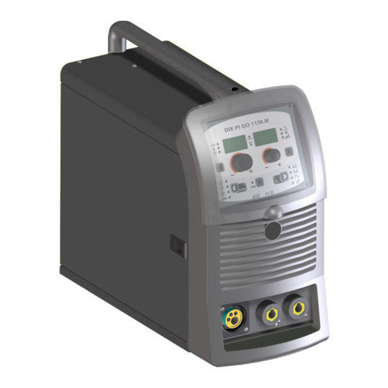
Command and control units (Fig. A) Innovative, versatile, light-weight, easily portable, simple to use, DIX PI GO 1156.M is a very high level product that is abso- Loading wire lutely irreplaceable technologically for all internal and external Assembly of drive roller... -
Page 3: Technical Data
The general technical data of the system are summarized in the equipment are moving. table 1. Table 1 DIX PI GO 1156.M Model MIG-MAG Single-phase input 50/60 Hz 230 ± 15% Mains supply: Z Ω... -
Page 4: How To Lift Up The Welding Power Source
• Connect the welding welding power source to the utility line. wise and aligning the protruding marker on the support with • Connect up the welding cables. the relevant hole in the coil. Table 2 DIX PI GO 1156.M Model MIG-MAG Power input (I Max) Delayed fuse (I eff) Duty cycle @ X% (40°C) -
Page 5: Assembly Of Drive Roller
• Thread the end of the wire into the back guide (Pos. 7, Fig. B) on the drawing mechanism. • Lift up the idle roller Ø 26 mm (Pos. 1, Fig. B) releasing the roller pressure mechanism (Pos. 6, Fig. B). Check that the drive roller (Pos. -
Page 6: Mig-Mag Welding Without Gas
a pressure reducer to adjust pressure of the gas used for welding. 2) Screw the torch to the centralised connection on the front panel of the welding welding power source (Pos. 4, Fig. A). 3) Connect up the earthing system cable to the rapid cou- pling marked by a - (negative) symbol and then the rel- evant ground clamps to the piece being welded or to its support in an area free from rust, paint and grease. -
Page 7: Spot Welding
an area free from rust, paint and grease. Using particularly long earthing cables reduces the voltage and causes some problems from increased resistance and inductance of the cables that could cause faulty welding. Follow instructions to avoid these problems: • Use earthing and extension cables with appropriate sec- tion. -
Page 8: Interval Welding (Stitch)
- Connect the ground cable to the snap-on connector Interval welding (Stitch) marked + (positive). - Connect the relative ground clamp to the workpiece or The substantial differences with the spot welding mainly con- to the workpiece support in an area free of rust, paint, cern the adjustments that must be carried on the welding weld- grease, etc.. -
Page 9: Maintenance
The values of current to use are shown in the table with the respec- DIX PI GO 1156.M tive electrodes for the welding of common steels and low-grade IMPORTANT: Since the welding welding power sources are ful- alloys. -
Page 10: The Pointing Out Of Any Difficulties And Their Elimination
The pointing out of any difficulties and their elimination The supply line is attributed with the cause of the most com- mon difficulties. In the case of breakdown, proceed as follows: 1) Check the value of the supply voltage. 2) Check that the power cable is perfectly connected to the plug and the supply switch. -
Page 11: Troubleshooting Table
Troubleshooting table WARNING: Any internal inspections or repairs are only to be done by qualified personnel! IMPORTANT: Remember to disconnect the mains power supply and wait for the internal capacitors to discharge (about 2 min- utes) before starting to check and repair the welding power source if necessary. Defect Solution • Check that the welding welding power source is installed correctly and that the... -
Page 13: Electro Topographical Diagram Key
•1 •2 •3 •4 •5 •6 •7 •8 •9 •10 •11 L1-2-3 •12 •13 •14 •15 •16 •17 •18 •19 •20 •21 •22 Electro topographical diagram key Colour key •1 Primary transformer coil •2 Secondary transformer coil •3 Polarity change Orange terminal board •4 Gas solenoid valve •5 Mains switch •6 Secondary induct- Sky Blue... - Page 14 Control panel Welding Power Source 4 - PRE-SETTING Introduction 5 - WELDING KEY AND KNOB COMMANDS 6 - HOLD Control panel Special processes DISPLAY AND LED INDICATIONS Electrode (MMA) Switching on the welding power source and initial 1 - WELDING PROCESS SELECTION screen 2 - SELECTION OF WELDING PROGRAM 3 - SPECIAL FUNCTIONS “Fx”...
-
Page 15: Key And Knob Commands
TWO STROKE (2T) Control panel 2T LED ( ) switched on Pressing the TORCH TRIGGER starts the welding cycle, which will stop when it is released. KEY AND KNOB COMMANDS FOUR STROKE (4T) ▪ ENCODER knob - A ▪ ENCODER knob - V 4T LED ( ) switched on 1) Pressing and releasing the TORCH TRIGGER will start the... -
Page 16: Display And Led Indications
■ SPECIAL FUNCTIONS key “Fx” (T ≥ 2 s) ■ PARAMETER DISPLAY screen - V This key is used to display and edit some parameters (ADJUST- This Display shows the values / numbers (set or measured) of the ABLE FUNCTIONS “Fx”) that are necessary and fundamental for following parameters (if active): • ARC LENGTH ADJUSTMENT ( welding and that have already been set by the manufacturer in... -
Page 17: Loading Of The Wire
2) On both displays appears a running string that indicates the WARNING: Changes to values are immediately activated (no fur- VERSION OF THE SOFTWARE installed on the welder. ther confirmation is required and they will be displayed immedi- The rotation of one of the two ENCODER Knobs - A (E1) or ately) or, at least they will become active the next time welding is V (E2) by the operator during the display of the string version done. - Page 18 Table 1 SETTINGS RANGE WELDING PROCESS MIG-MAG WELDING MODE MIG MAG / PULSE FUNCTION DISPLAY Spot Stitch FACTORY RANGE Cycle ADJUSTABLE FUNCTIONS “Fx” Fx > 3s MIG-MAG process PRE GAS 0.1s (0.0 ÷ 2.0)s ● ● ● ● ● ● ●...
-
Page 19: Setup Menu
3) To exit the SPECIAL FUNCTIONS “Fx” menu, push and re- TIMER ARC ON lease the SPECIAL FUNCTIONS “Fx” (T3) key once. This indicates the actual time the machine was used for welding. WARNING: This time can only be zeroed using the FACTORY DE- FAULT (FAC in the SEtUP menu) for the welding plant. -
Page 20: Error Log
ERROR LOG TEST This allows the operator to know about the error states that have This configuration allows the operator to check that some func- arisen on the welding plant. tions of some devices. 1) Rotate the ENCODER - A (E1) knob, until both the displays 1) Rotate the ENCODER - A (E1) knob, until both the displays (D1-D2) read Err Log. -
Page 21: Menu Special Functions
MOTOR CALIBRATION (Mot CAL) Menu SPECIAL FUNCTIONS From the SEtUP menu, push the PRG key (T5) for more than 3 ATTENTION: This procedure allows you to calibrate the wire seconds to access the SPECIAL FUNCTIONS menu, which pro- speed (only in MIG welding processes). vides access to additional functions that can only be managed by an expert, responsible operator. -
Page 22: Arc Length Adjust
Calibration parameter SM3 (MAXIMUM SPEED) CYCLE Then turn the ENCODER - A knob (E1) until the PARAM- If enabled, this function allows the operator to have a further ETER DISPLAY - A screen (D1) shows the SM3 parame- welding mode (CYCLE) available, in MIG (pulsed, double pulsed, ter. -
Page 23: Password
RAMETERS - A (D1) display shows the SEr function, and the DISPLAY PARAMETERS - V (D2) display reads nUM. IMPORTANT: If the password is lost, contact DINSE it’s tech- nical service department. 2) When the PRG key is pushed, a 16-character text will pass... -
Page 24: Mig-Mag Synergic / Mig Pulse / Double Pulsed Mig
2 - SELECTION OF WELDING PROGRAMME MIG-MAG synergic / MIG pulse / double pulsed MIG PROGRAM TABLE MIG-MAG-PULSE PROCESS Start the welder by pressing the switch, located on the back pan- el, at the position I. MATERIAL DISPLAYS PROGRAM WIRE Ø 1 - WELDING PROCESS SELECTION NUMBER (mm) -
Page 25: Welding Mode Selection
■ PROGRAM DEFAULT (dEF) 3 - WELDING MODE SELECTION Select the MODE of welding, pressing and releasing, even various times if necessary, the WELDING MODE SELECTION key (T3) WARNING: If carried out, this operation resets the program until the corresponding LED lights up. in use to the factory default settings. -
Page 26: Pre-Setting
5 - PRE-SETTING During the welding the operator can change the following param- eters: Before welding it is possible to set the following parameters: • THICKNESS OF WELDED ITEM ( • WELDING CURRENT ( ). THICKNESS OF WELDED ITEM • WIRE SPEED ( • ARC LENGTH ADJUSTMENT ( WELDING CURRENT • ELECTRONIC INDUCTANCE (... -
Page 27: Mig-Mag Manual
• CRATER START TIME (F10) - This function defines the time MIG-MAG manual in which the current remains at the value of CRATER START SPEED or CRATER START VOLTAGE. Start the welder by pressing the switch, located on the back pan- • CRATER START SLOPE (F11) - Time taken to go from the CRA- el, at the position I. -
Page 28: Pre-Setting
• Hold the SAVE “MEM” key (T2) down for at least 2 consecu- • PARAMETER DISPLAY screen - V (D2) tive seconds. T ≥ 2 s WELDING VOLTAGE ELECTRONIC INDUCTANCE • The program in use has now been completed successfully. To confirmation the above, the control panel of the welder performs a short operation of MACHINE CHECK (all of the LED stay lit simultaneously so as to verify their actual operation), the gen-... -
Page 29: Special Processes
To interrupt the HOLD function and go back to the PRESETTING WELDING PROCESS SELECTION key (T2) until the correspond- phase before 15 seconds have passed, simply turn one of the two ing LED lights up. ENCODER knobs (E1-E2). Push the SELECT PROGRAM key (T5). The corresponding LED switches on. -
Page 30: Pre-Setting
The SPECIAL FUNCTIONS “Fx” that are only available in the MMA Example: WELDING CURRENT welding process are shown below. For all the other explanations Press the PARAMETER SELECTION - A key (T1) until the LED regarding this menu make reference to the relative paragraph. that corresponds to the WELDING CURRENT switches on. -
Page 31: Activating The Vrd Device
WELDING CURRENT - WELDING CURRENT ( ): the last current value measured. • PARAMETER DISPLAY screen - V (D2) HOT START WELDING VOLTAGE ARC FORCE • HOT START ( ): the value previously set. • WELDING VOLTAGE ( ): the measured value of the last volt- age of what is being previously welded. -
Page 32: Pre-Setting
• Rotate the ENCODER - A (E1) knob until both the displays read dEF no (see figure). WELDING CURRENT - WELDING CURRENT ( ): the measured value of the current of what is being welded. • PARAMETER DISPLAY screen - V (D2) • Rotate the ENCODER - V knob (E2) until the PARAMETERS DISPLAY - V screen (D2) reads YES. -
Page 33: Job
The HOLD function can be terminated ahead of time even once 2) Hold down the SAVE “MEM” (T2) Key down for at least 2 con- again starting the welding. secutive seconds to save JOB and automatically load the set- Once 15 seconds have passed (HOLD FUNCTION) the control tings / parameters (including special functions) for the JOB just panel goes back to the PRESETTING phase. -
Page 34: Hold
As already indicated, the parameters can be viewed by pressing and releasing the PARAMETER SELECTION key - A (T1) or in al- ternative the PARAMETER SELECTION key - V (T4), while the SPECIAL FUNCTIONS “Fx” key (T3) contained within each indi- vidual JOB can be viewed (but not modified) by simply keeping the SPECIAL FUNCTIONS “Fx”... - Page 35 ▪ ERROR CONDITION display ▪ ERROR DESCRIPTION display Error condition Error code Error description and possible diagnosis POWER LIMITATION This alarm appears if the power limit is exceeded. The alarm alternates with the standard display every 1.5 seconds, despite which the machine continues to weld, supplying limited power, but complying with the values shown on the data plate.
- Page 36 Error condition Error code Error description and possible diagnosis MIG SYN SPECIAL FUNCTION “Fx” WRONG E4.2 NON automatic reset error. Immediately contact technical assistance dept. MIG MAN SPECIAL FUNCTION “Fx” WRONG E4.3 NON automatic reset error. Immediately contact technical assistance dept. SPECIAL “Fx”...
Need help?
Do you have a question about the DIX PI GO 1156.M and is the answer not in the manual?
Questions and answers