Chapters
Table of Contents

Subscribe to Our Youtube Channel
Related Manuals for DINSE DIX PI 3006.M I


Summary of Contents for DINSE DIX PI 3006.M I
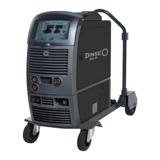
- Page 1 Operations manual Welding Power Source DIX PI 3006.M I DIX PI 3506.M I DIX PI 3006.M I Puls DIX PI 3506.M I Puls Keep in secure area for future reference! S C H W E I S S E N...
-
Page 2: Table Of Contents
The pointing out of any difficulties and their elimination 9 ing purposes that call for high precision and repeatable results. DIX PI 3506.M I / DIX PI 3006.M I Puls / DIX PI 3506.M I Puls Replacing the digital interface PCB equipments, fitted with the extraordinary DIX.ARC meet the... -
Page 3: Technical Data
After several minutes the overheat cut- off rearms automatically and the welder is ready for use again. Table 1 DIX PI 3006.M I DIX PI 3506.M I DIX PI 3006.M I Puls DIX PI 3506.M I Puls Model MIG/MAG welding Three-phase input 50/60 Hz 400 ±... -
Page 4: How To Lift Up The System
Connection of the welding power source to the user line The system essentially consists of: (electrical current) must be performed by qualified per- • DIX PI 3506.M I / DIX PI 3006.M I Puls / DIX PI 3506.M I sonnel. Puls weld unit. -
Page 5: Loading Wire
Loading wire • Fit the reel (diam. 300 mm) on the support so that the wire unrolls clockwise, and center the projecting reference on the 3 4 4 3 support with the relative hold on the reel. • Thread the end of the wire into the back guide (Pos. 1, Fig. A) on the drawing mechanism. -
Page 6: Mig-Mag / Puls Mig / Double Puls Mig Welding
2 - Welding 1) Switch the welding welding power source on by moving the power supply switch to I (Pos. 6, Fig. B). 2) Make the adjustments and do the parameter settings on the control panel. 3) Load the wire using the torch button, after having removed the wire guide nozzle from the torch to allow the wire to come out freely, while loading (remember that the wire guide nozzle must correspond to the diameter of the wire... -
Page 7: Aluminium Welding
Electrode welding (MMA) On the DIX PI 3506.M I / DIX PI 3006.M I Puls / DIX PI 3506.M I Puls welding power source, electrode welding is used to weld most metals (different types of steel, etc.) using coated rutilic and basic electrodes with diameters ranging from Ø... -
Page 8: Tig Welding With "Lift
We are not liable for damage due to use of spare fore effecting any internal inspection. parts that are not original. DIX PI 3006.M I / DIX PI 3506.M I / DIX PI 3006.M I Puls / Optional DIX PI 3506.M I Puls... -
Page 9: The Pointing Out Of Any Difficulties And Their Elimination
The pointing out of any difficulties and their elimination The supply line is attributed with the cause of the most com- mon difficulties. In the case of breakdown, proceed as follows: 1) Check the value of the supply voltage. 2) Check that the power cable is perfectly connected to the plug and the supply switch. -
Page 10: Troubleshooting Table
Troubleshooting table WARNING: Any internal inspections or repairs are only to be done by qualified personnel! IMPORTANT: Remember to disconnect the mains power supply and wait for the internal capacitors to discharge (about 2 min- utes) before starting to check and repair the welding power source if necessary. Defect Solution • Check that the welding welding power source is installed correctly and that the... -
Page 11: Meaning Of Graphic Symbols On Welding Power Source
Meaning of graphic symbols on welding power source Negative pole snap-in connector Power supply switch System for use in environments with in- Warning! creased risk of electroshock Before using the equipment you should Product suitable for free circulation in the carefully read the instructions included in European Community this manual... -
Page 14: Introduction
Control panel Welding Power Source Introduction Special processes Control panel Electrode (MMA) KEY AND KNOB COMMANDS 1 - WELDING PROCESS SELECTION DISPLAY AND LED INDICATIONS 2 - SELECTION OF WELDING PROGRAM 3 - SPECIAL FUNCTIONS “Fx” SELECTION Switching on the welding machine and initial screen 16 4 - PRE-SETTING 5 - WELDING Viewing the software version installed... -
Page 15: Control Panel
TWO STROKE (2T) Control panel 2T LED ( ) switched on Pressing the TORCH TRIGGER starts the welding cycle, which will stop when it is released. KEY AND KNOB COMMANDS FOUR STROKE (4T) ▪ ENCODER knob - A ▪ ENCODER knob - V 4T LED ( ) switched on 1) Pressing and releasing the TORCH TRIGGER will start the... -
Page 16: Display And Led Indications
■ SPECIAL FUNCTIONS key “Fx” (T ≥ 2 s) ■ JOB SAVING MEM LED This key is used to display and edit some parameters (ADJUST- Flashes while saving a JOB. ABLE FUNCTIONS “Fx”) that are necessary and fundamental for ■ Fx LED - SPECIAL FUNCTIONS welding and that have already been set by the manufacturer in Switched on when special Fx parameters are displayed. -
Page 17: Loading Of The Wire
2) PROGRAM DEFAULT (dEF) 3) Ending viewing of the software version on the control panel can come about in 2 different ways: • Automatically: by waiting for the display time to elapse. WARNING: If carried out, this operation resets the program • Manually: by pushing any key. - Page 18 Table 1 SETTINGS RANGE WELDING PROCESS MIG-MAG WELDING MODE MIG MAG / PULSE FUNCTION DISPLAY Spot Stitch FACTORY RANGE SWITCH ADJUSTABLE FUNCTIONS “Fx” Fx > 3s MIG-MAG process PRE GAS 0.1s (0.0 ÷ 2.0)s ● ● ● ● ● ● ●...
-
Page 19: Setup Menu
SETUP Menu Hold the PRG key down for at least 3 seconds to open the SET- UP menu, which provides access to various functions, which are suitable for expert operators, such as advanced configurations, system tests, and calibrations. For further information, see table 1. FACTORY DEFAULT (FAC) WARNING: If carried out, this operation results in complete resetting of all editable parameters to the factory settings (in-... -
Page 20: Test
1) Rotate the ENCODER - A (E1) knob, until both the displays (D1-D2) read tESt. 2) Push the PRG key (T5), and the display will show the error code under DISPLAY PARAMETERS - A (D1), and the num- ber of times under DISPLAY PARAMETERS - V (D2). For the 2) Push the PRG key (T5), and the display will show the param- code error, see the list contained in the “Error Conditions”... -
Page 21: Menu Special Functions
MOTOR CALIBRATION (Mot CAL) Menu SPECIAL FUNCTIONS From the SEtUP menu, push the PRG key (T5) for more than 3 ATTENTION: This procedure allows you to calibrate the wire speed (only in MIG welding processes). seconds to access the SPECIAL FUNCTIONS menu, which pro- vides access to additional functions that can only be managed by an expert, responsible operator. -
Page 22: Arc Length Adjust
Calibration parameter SM3 (MAXIMUM SPEED) SWITCH Then turn the ENCODER - A knob (E1) until the PARAM- If enabled, this function allows the operator to have a further weld- ETER DISPLAY - A screen (D1) shows the SM3 parame- ing mode (SWITCH) available, in MIG (pulsed, double pulsed, ter. -
Page 23: Password
RAMETERS - A (D1) display shows the SEr function, and the DISPLAY PARAMETERS - V (D2) display reads nUM. IMPORTANT: If the password is lost, contact DINSE it’s tech- nical service department. 2) When the PRG key is pushed, a 16-character text will pass... -
Page 24: Mig-Mag Synergic / Mig Pulse / Double Pulsed Mig
2 - SELECTION OF WELDING PROGRAMME MIG-MAG synergic / MIG pulse / double pulsed MIG PROGRAM TABLE MIG-MAG-PULSE PROCESS Start the welder by pressing the switch, located on the back pan- el, at the position I. MATERIAL DISPLAYS PROGRAM WIRE Ø 1 - WELDING PROCESS SELECTION NUMBER (mm) -
Page 25: Welding Mode Selection
■ PROGRAM DEFAULT (dEF) 3 - WELDING MODE SELECTION Select the MODE of welding, pressing and releasing, even various times if necessary, the WELDING MODE SELECTION key (T3) WARNING: If carried out, this operation resets the program until the corresponding LED lights up. in use to the factory default settings. -
Page 26: Pre-Setting
5 - PRE-SETTING During the welding the operator can change the following param- eters: Before welding it is possible to set the following parameters: • THICKNESS OF WELDED ITEM ( • WELDING CURRENT ( ). THICKNESS OF WELDED ITEM • WIRE SPEED ( • ARC LENGTH ADJUSTMENT ( WELDING CURRENT • ELECTRONIC INDUCTANCE (... -
Page 27: Mig-Mag Manual
• CRATER START TIME (F10) - This function defines the time MIG-MAG manual in which the current remains at the value of CRATER START SPEED or CRATER START VOLTAGE. Start the welding power source by pressing the switch, located on • CRATER START SLOPE (F11) - Time taken to go from the CRA- the back panel, at the position I. -
Page 28: Pre-Setting
• Hold the SAVE “MEM” key (T2) down for at least 2 consecu- • PARAMETER DISPLAY screen - V (D2) tive seconds. T ≥ 2 s WELDING VOLTAGE ELECTRONIC INDUCTANCE • The program in use has now been completed successfully. To confirmation the above, the control panel of the welder performs a short operation of MACHINE CHECK (all of the LED stay lit simultaneously so as to verify their actual operation), the gen-... -
Page 29: Special Processes
To interrupt the HOLD function and go back to the PRESETTING WELDING PROCESS SELECTION key (T2) until the correspond- phase before 15 seconds have passed, simply turn one of the two ing LED lights up. ENCODER knobs (E1-E2). Push the SELECT PROGRAM key (T5). The corresponding LED switches on. -
Page 30: Pre-Setting
The SPECIAL FUNCTIONS “Fx” that are only available in the MMA Example: WELDING CURRENT welding process are shown below. For all the other explanations Press the PARAMETER SELECTION - A key (T1) until the LED regarding this menu make reference to the relative paragraph. that corresponds to the WELDING CURRENT switches on. -
Page 31: Activating The Vrd Device
WELDING CURRENT - WELDING CURRENT ( ): the last current value measured. • PARAMETER DISPLAY screen - V (D2) HOT START WELDING VOLTAGE ARC FORCE • HOT START ( ): the value previously set. • WELDING VOLTAGE ( ): the measured value of the last volt- age of what is being previously welded. -
Page 32: Pre-Setting
• Rotate the ENCODER - A (E1) knob until both the displays read dEF no (see figure). WELDING CURRENT - WELDING CURRENT ( ): the measured value of the current of what is being welded. • PARAMETER DISPLAY screen - V (D2) • Rotate the ENCODER - V knob (E2) until the PARAMETERS DISPLAY - V screen (D2) reads YES. -
Page 33: Job
The HOLD function can be terminated ahead of time even once 2) Hold down the SAVE “MEM” (T2) Key down for at least 2 con- again starting the welding. secutive seconds to save JOB and automatically load the set- Once 15 seconds have passed (HOLD FUNCTION) the control tings / parameters (including special functions) for the JOB just panel goes back to the PRESETTING phase. -
Page 34: Hold
As already indicated, the parameters can be viewed by pressing and releasing the PARAMETER SELECTION key - A (T1) or in al- ternative the PARAMETER SELECTION key - V (T4), while the SPECIAL FUNCTIONS “Fx” key (T3) contained within each indi- vidual JOB can be viewed (but not modified) by simply keeping the SPECIAL FUNCTIONS “Fx”... - Page 35 ▪ ERROR CONDITION display ▪ ERROR DESCRIPTION display Error condition Error code Error description and possible diagnosis POWER LIMITATION This alarm appears if the power limit is exceeded. The alarm alternates with the standard display every 1.5 seconds, despite which the machine continues to weld, supplying limited power, but complying with the values shown on the data plate.
- Page 36 Error condition Error code Error description and possible diagnosis MIG SYN SPECIAL FUNCTION “Fx” WRONG E4.2 NON automatic reset error. Immediately contact technical assistance dept. MIG MAN SPECIAL FUNCTION “Fx” WRONG E4.3 NON automatic reset error. Immediately contact technical assistance dept. SPECIAL “Fx”...
Need help?
Do you have a question about the DIX PI 3006.M I and is the answer not in the manual?
Questions and answers