Table of Contents
Advertisement
Quick Links
Advertisement
Table of Contents

Related Manuals for SolidRun ClearFog PRO

Summary of Contents for SolidRun ClearFog PRO
- Page 1 ClearFog User Manual...
-
Page 2: Table Of Contents
Connector Layout ............................... 7 Certified Cables ..............................8 Installation and Switching On ..........................9 Unpacking your SolidRun ClearFog Pro ......................9 Power ................................... 9 SD card with operating system and boot select ..................9 MicroUSB connectivity (UART to microUSB) ..................... 10 LEDs ................................... - Page 3 To the extent permitted by law no liability (including liability to any person by reason of negligence) will be accepted by SolidRun Ltd., its subsidiaries or employees for any direct or indirect loss or damage caused by omissions from or inaccuracies in this document. SolidRun Ltd. reserves the right to change details in this publication without prior notice.
-
Page 4: Overview
The SolidRun ClearFog Pro is a high performance platform featuring SolidRun’s SOM (A388 SOM). ClearFog Pro provides a foundation for building various applications and tailors well to a wide range of target markets requiring high performance processing power, connectivity & storage interfaces. The ClearFog Pro ensures compact dimensions and low power consumption, utilizing an ARM Cortex A9 Dual core CPU. -
Page 5: Block Diagram
ANUAL ARCH 2.3 B LOCK IAGRAM The SolidRun ClearFog Pro Single Board Computer block diagram displays all relevant elements of the full SBC. For further details please visit www.solid-run.com and wiki.solid-run.com: Figure 1 SolidRun ClearFog Pro Block Diagram SolidRun Ltd www.solid-run.com... -
Page 6: Main Hardware Components
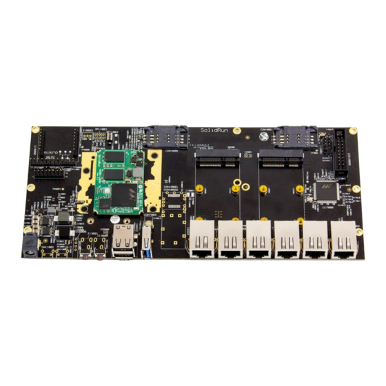
2017 ANUAL ARCH ARDWARE OMPONENTS This chapter highlights the location of the main hardware components and interfaces of the SolidRun ClearFog Pro, including the A388 SOM: Figure 2 SolidRun ClearFog Pro Top View SolidRun Ltd www.solid-run.com Page 6 of 22... - Page 7 2017 ANUAL ARCH Figure 3 SolidRun ClearFog Pro Bottom View SolidRun Ltd www.solid-run.com Page 7 of 22 7 HaMada Street, Yokne’am Illit, Israel...
-
Page 8: Connector Layout
The following is a list of industry-standard cables, sorted by type, with the necessary compliance requirements that have been proven to work well with the Clearfog product family. These examples are the cables which SolidRun uses for testing, and should provide enough information to source products from your prefered cable vendor. -
Page 9: Installation And Switching On
CARD WITH OPERATING SYSTEM AND BOOT SELECT You will need to download an operating system for the ClearFog Pro and flash in to a blank SD card in order to use the system. You can download official release distributions and find flashing instructions at https://www.solid-run.com/downloads/. -
Page 10: Microusb Connectivity (Uart To Microusb)
CONNECTIVITY TO MICRO The ClearFog Pro Single Board Computer has an FTDI 230x UART to USB bridge allowing convenient connection to the device console. This configuration is typically used by developers for debugging purposes (e.g. kernel or drivers). Such serial console connection is of USB-to-UART type. The connection speed should be set to 115200 bps. -
Page 11: Sim Card Slot
GSM Cellular modem needs to be installed utilizing the mini PCIe connection in order to exploit the cellular connection. Please note: If you your ClearFog Pro has dual SIM card slots, an additional cellular modem will need to be installed in the mini PCIe connection in order to utelize the 2nd SIM connection. -
Page 12: Operational Data
+85°C*** Humidity (non-condensing) Note: Environmental data ranges are based solely on the ClearFog Pro components. The customer needs to consider specific thermal and mechanical design for a final product, including but not limited to housing, taking into account specific operational and environmental conditions. -
Page 13: Mechanical Drawings And Dimensions
ECHANICAL RAWINGS AND IMENSIONS For product design purposes, this chapter provides the SolidRun ClearFog Pro dimensions and component positions on both sides of the board: Figure 7 ClearFog Pro Mechanical Drawings & Dimensions CAD files are available for download at wiki.solid-run.com... -
Page 14: Warranty Terms And Conditions
SolidRun guarantees its hardware products against defects in workmanship and material for a period of one (1) year from the date of shipment. Under warranty, the customer’s sole remedy and SolidRun’s sole liability shall be, at SolidRun’s sole discretion, to either repair or replace the defective hardware product at no charge. -
Page 15: Legal Notice
Customers should make sure to obtain in each case the latest version of relevant product information from SolidRun and to always verify for themselves that their requirements are met and reference is up to date. Product testing and all additional quality control techniques are utilized to the extent that SolidRun deems necessary to support their warranty and warranty terms. -
Page 16: Egulatory
You are responsible if the product is used for any intention other than its designated purpose or in disregard of SolidRun instructions. SolidRun shall assume no responsibility for such use of the product. The product is used for its designated purpose if it is used in accordance with its product documentation and within its performance limits. -
Page 17: Unpacking
Never remove the cover or any part of the housing of the product The internal battery is not user replicable. In the event of an equipment malfunction, all repairs must be performed either by SolidRun or by an authorized agent. It is the customer responsibility to report the need for service to SolidRun or to one of the authorized agents. -
Page 18: Operation
The product operating ambient range is temperature of 0-40 °C (32 to 104 °F) and Relative humidity of 10- 90%. SolidRun recommends that an ambient temperature of 20 to 25 °C (68 to 77 °F) and relative humidity of 30-50% is maintained during normal operation as this will result in better performance and longer life of the equipment. -
Page 19: Ac/Dc Adapter Or Power Supply - Electrical Safety
Prior to cleaning the product, disconnect it completely from the power supply. Use a soft, non-linting cloth to clean the product. Never use chemical cleaning agents such as alcohol, acetone or diluents for cellulose lacquers. SolidRun Ltd www.solid-run.com Page 19 of 22... -
Page 20: Electronic Emission Notices
20 April, 2016) on the approximation of the laws of the Member States relating to electromagnetic compatibility. SolidRun Ltd. is not responsible for any radio or television interference caused by using other than specified or recommended cables and connectors or by unauthorized changes or modifications to this equipment. - Page 21 ARCH Appendix B. WEEE and recycling statements The WEEE marking on SolidRun Ltd. products applies to countries with WEEE and e-waste regulations (for example, the European WEEE Directive,). Appliances are labeled in accordance with local regulations concerning waste electrical and electronic equipment (WEEE).
-
Page 22: Ontact Nformation And Esources
2017 ANUAL ARCH ONTACT NFORMATION AND ESOURCES SolidRun Ltd Headquarters #7 HaMada St Yokne’am Illit 2069201 Israel Web page: http://www.solid-run.com Wiki page: wiki.solid-run.com Support: support@solid-run.com Sales: sales@solid-run.com SolidRun Ltd www.solid-run.com Page 22 of 22 7 HaMada Street, Yokne’am Illit, Israel...
Need help?
Do you have a question about the ClearFog PRO and is the answer not in the manual?
Questions and answers