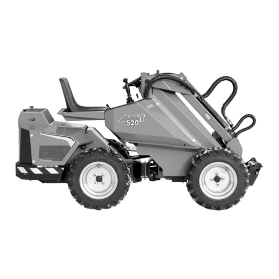
AVANT 500 Series Operator's Manual
Articulated compact loader
Hide thumbs
Also See for 500 Series:
- Operator's manual (40 pages) ,
- Operator's manual (26 pages) ,
- Operator's manual (26 pages)
Table of Contents
Advertisement
Advertisement
Table of Contents

Related Manuals for AVANT 500 Series


Summary of Contents for AVANT 500 Series
- Page 1 English series Operator’s Manual 2018-...
-
Page 2: Table Of Contents
Table of contents 500 Series TABLE OF CONTENTS Table of contents............2 Drive control............22 Introduction..............3 Steering of the machine.........23 Safety instructions............4 Loader control............23 Warranty..............6 Using the auxiliary hydraulics........23 Description of the loader..........7 Requirements for attachments......24 Engine identification..........7 Coupling the attachments........24 Loader identification..........7 Hydraulic attachment coupling plate.....24... -
Page 3: Introduction
Keep this Operators Manual with the machine at all times. If this Manual gets lost, ask for a new copy from your Avant dealer. Remember also to give this Manual to the new owner when the machine changes ownership. -
Page 4: Safety Instructions
Do not transport or lift persons in the bucket or in any well as the safety instructions. other attachment. Lifting of persons is only allowed with the attachment designed for this purpose: Avant Understand the limitations of speed, braking, steering and Leguan 50, following the instructions in the Operators stability as well as loading capacity of the machine before Manual of Leguan 50. - Page 5 500 Series Safety instructions Handling of heavy loads Electric system and handling the battery Never take a heavy load on the loader from Lead acid batteries can produce flammable and explosive high level – e.g. from truck, shelf etc. – risk of gases.
-
Page 6: Warranty
During the first two years of operation or first 1000 hours is ensured, keep the electric parts clean. Overheating (whichever is the soonest) Avant Tecno Oy warrants to of electric parts can shorten their service life. replace any part or repair any defect which may occur, subject to the terms detailed below: •... -
Page 7: Description Of The Loader
500 Series Description of the loader Description of the loader Identification of the loader Write down the identification information of your loader in the following fields, it facilitates ordering of spare parts etc. 1. Loader model_____________________________________________ 2. Loader serial no.___________________________________________ 3. -
Page 8: Main Parts Of The Loader
Description of the loader 500 Series Main parts of the loader Following picture shows the main parts of the loader: Hydraulic connectors Multi connector Pressure 2 Pressure 1 Tank line Attachment control switch pack socket (option) Attachment coupling plate Front frame Attachments are mounted on the attachment coupling On the front frame are mounted: driver’s seat,... -
Page 9: Signs And Decals
Signs and decals Make sure that the following signs and decals clean, undamaged and readable. If any of these decals is missing or is unreadable it should be replaced without delay. Ask for new decals from your local Avant dealer. -
Page 10: Technical Specification
Description of the loader 500 Series Technical specification Model AVANT 520 AVANT 523 AVANT 528 AVANT 530 Length 2430 mm 2430 mm 2550 mm 2550 mm Width see table see table see table see table Height 1985 mm 1985 mm... -
Page 11: Engine Specification
500 Series Description of the loader Engine specification Model 528 / 530 Engine make and type Kubota D722 Kubota D902 Kubota D1105 Function 4-stroke 4-stroke 4-stroke Coolant Water Water Water Number of cylinders Starter electric electric electric Bore x stroke... -
Page 12: Load Diagram
Description of the loader 500 Series Load diagram The lifting capacity of the loader is limited by the possibility of tipping around the front axle. The diagram below shows the tipping loads and max. allowed loads in different loading situations on an even level surface with the loader chassis in maximum articulation. -
Page 13: Operating Instructions
500 Series Operating instructions Operating instructions... -
Page 14: Operating Controls
Operating instructions 500 Series Operating controls Following picture shows the location of operating controls. The location and function of controls may be slightly different in different models, see following pages. Cab DLX: Some of the switches are on the panel in the cab. -
Page 15: Control Of Loader Boom, Auxiliary Hydraulics And Other Functions
500 Series Operating instructions Control of loader boom, auxiliary hydraulics and other functions Most of the functions of the loader are controlled at the control panel on the right side of the operator: Boom and bucket movements, auxiliary hydraulics (attachments), engine revs etc. , depending on loader model. Following pictures show the... -
Page 16: Dashboard
Operating instructions 500 Series Dashboard On the dashoard on the right side of the driver’s seat are mounted gauges, indicators and switches which help the operator to control the loader. Cab LX /DLX ROPS 2. Boom floating indicator 3. Headlights indicator 4. -
Page 17: Controls In The Footwell
500 Series Operating instructions Controls in the footwell Air suspension seat (option for cab DLX) Following picture shows the controls located in the footwell To adjust the air suspension seat, sit on the seat and switch the ignition switch to “ON”. Check the indicator on front of the seat. -
Page 18: Drive Speed Range Selection Switch
Operating instructions 500 Series Drive speed range selection switch Seat heater Avant 530 is equipped with two-speed hydraulic drive The suspension seat is equipped motors. Drive speed range can be selected with the switch with an electric seat heater. Seat on the control panel right (see page 14). -
Page 19: Boom Floating
Hydraulic rear lifing device comes This optional equipment enables with a double acting auxiliary hydraulics outlet. road traffic registration in certain countries. Requirements vary in different countries, please consult your local AVANT distributor. -
Page 20: Tilt Adapter
Operating instructions 500 Series Tilt adapter (option) Extra auxiliary hydraulics outlets, front and rear (option) The hydraulic tilt adapter mounts between the attachment and the In addition to the standard auxiliary hydraulics outlet, attachment coupling plate. It allows the loader can be equipped with a double acting extra the driver to tilt the attachment outlet. -
Page 21: Starting The Engine
500 Series Operating instructions Starting the engine Before starting the engine do the daily checks, see page 27. Adjust the seat and mirrors (if fitted) so that you have a good working position and unrestricted field of vision from the driver’s seat. Check that all controls function correctly. See to it that the operating area is safe. -
Page 22: Drive Control
Principle of operation AVANT 520/523/528/530 is equipped with a hydrostatic drive system, a variable displacement hydraulic pump in the drive circuit is proportianally controlled with the two drive pedals. Driving of the machine is controlled with the drive pedals and hand throttle. -
Page 23: Steering Of The Machine
500 Series Operating instructions Steering of the machine Loader control Steering of the machine happens with the steering wheel. The loader boom and bucket are controlled with the The steering wheel is hydraulically powered. A practical multi-function lever sideways (tilt) and back & forward way of steering is to steer with your left hand on the knob (boom up &... -
Page 24: Requirements For Attachments
• Read Operators Manual of the attachment before starting operation. Make sure that the attachment is compatible with the loader. Contact your Avant dealer if necessary • Check max. allowed hydraulic oil flow for the attachment. Adjust engine revs so that they are suitable for the work and the attachment. -
Page 25: Coupling The Hydraulic Hoses Of The Attachment
500 Series Operating instructions Coupling the hydraulic hoses of the attachment Hydraulic hoses of the attachment are equipped with the multi connector system, which connects all hoses at the same time. Coupling the multi connector Align the pins of the attachment connector with correspondig holes of the loader connector. -
Page 26: Cabs
Cabs Switches in cab DLX On CAB DLX some the AVANT 520/523/528/530 can be equipped, as an option, switches shown in detail on with cab L, LX or DLX. All cabs are ROPS and FOPS page 14 are located on the certified. - Page 27 500 Series Operating instructions Heater Safety Familiarise yourself with the special (cab LX) drive features and space needs of this Temperature articulated loader, equipped with cab, adjustment on a flat, even and open place. Remember that, when turning, the cab extends beyond the turning radius of the wheels.
-
Page 28: Service And Maintenance Instructions
Service and maintenance instructions 500 Series Service and maintenance instructions Service parts are available through your Avant dealer or authorized service. If you are not sure about how to do any service operation, ask for additional information before starting servicing. Contact Avant service. -
Page 29: Daily Inspections
500 Series Service and maintenance instructions Daily inspections • Tyre pressure • Locking of attachment and locking pins on attachment • Boom movements coupling plate, function of attachment, position of • Drive control and steering attachment hoses • Eventual need for lubrication •... -
Page 30: Cleaning Of The Machine
Service and maintenance instructions 500 Series 2. Cleaning of the machine 6. Check coolant level Cleanliness of the loader is not only a question of outer appearance. All surfaces, painted and others, will stay Never open the in better condition when they are cleaned regularly. A... -
Page 31: Check And Tightening Of Bolts, Nuts Etc
Warranty does not cover damages caused by cartridges which have fixed 350 bar (520/523/528) and excessive hydraulic pressure. 370 bar (530) pressure setting. It is recommended that pressures should only be checked by a competent and experienced technician. Call your AVANT dealer if you need assistance. -
Page 32: Adjust And Change Of Slide Pads On Telescopic Boom
Service and maintenance instructions 500 Series 12-14 Adjust and change the slide pads 15.-16. Clean air filter element on telescopic boom 1. Squeeze the rubber vent on the filter housing cover The telescopic boom is equipped with replaceable slide to drain water and dirt pads. -
Page 33: Service, Engine
Kubota Operator’s Manual burning fuse. Electric cables may be damaged. Contact supplied with the loader. service. Avant 520/523/528/530 is equipped with separate fuse boxes: Main fuse box L and ROPS located outside the cab, on the right side of the loader boom. -
Page 34: Hydraulic Oil Cooler Fan Fuse
If the indicator is lit, check to add fuel before the fuel tank gets empty. Should this the 25A fuse of the oil cooler fan. Contact Avant service happen, a manual bleeding must be performed before if necessary. -
Page 35: Greasing Points
500 Series Service and maintenance instructions Greasing points Following pictures show the location of greasing points. Greasing points pcs. Greasing points pcs. Lift cylinder, both ends Articulation joint Steering cylinder, both ends Tilting mechanism Tilt cylinder, both ends Leveling cylinder, both ends... -
Page 36: Filters
Service and maintenance instructions 500 Series Filters Following pictures and tables show the location and part numbers for the filters. Avant filters Avant 520 Avant 523 Avant 528/530 Air filter 64712 66516 64956 Fuel filter 64626 64626 64626 Fuel filter, pre filter... -
Page 37: Troubleshooting
500 Series Troubleshooting Troubleshooting Problem Possible cause Remedy Main switch off Turn on the main switch Battery discharged, battery voltage Check and charge too low Engine does not crank Check fuses. If fuse blows again, find out the cause. Blown fuse... -
Page 38: Service History
Services made 500 Series Services made 1. Customer_____________________________________________________ 2. Loader model_______________Serial no____________________________ 3. Date of delivery________________________________________________ Date of service Operating Serviced by: Remarks dd / mm / yyyy hours Stamp/signature ___/___/______ ______ / 50 h ___/___/______ ______ / 450 h... -
Page 39: Ec Declaration Of Conformity
500 Series EC Declaration of conformity 500 Series EC Declaration of conformity EC DECLARATION OF CONFORMITY 1. Manufacturer: Avant Tecno Oy Ylötie 1 FI-33470 YLÖJÄRVI FINLAND 2. We hereby declare that the machines listed below conform to EC Directives, as they are amended: 2006/42/EC (Machinery), 2014/30/EC (EMC) and 2000/14/EC (Noise Emission). - Page 40 Avant Tecno Oy Ylötie 1 FIN-33470 YLÖJÄRVI, FINLAND Tel. +358 3 347 8800 sales@avanttecno.com AVANT has a policy of continuing improvement, and retains the right to change specifications without notice. © 2018 AVANT Tecno Oy. Kaikki oikeudet pidätetään. www.avanttecno.com...
Need help?
Do you have a question about the 500 Series and is the answer not in the manual?
Questions and answers