Table of Contents
Advertisement
Quick Links
Advertisement
Table of Contents

Related Manuals for Moravian Instruments G3 Mark II Series


Summary of Contents for Moravian Instruments G3 Mark II Series
- Page 1 G3 Series Mark II Cooled CCD Cameras User’s Guide...
- Page 2 Version 1.3 Modified on August 12 , 2019 All information furnished by Moravian Instruments is believed to be accurate. Moravian Instruments reserves the right to change any information contained herein without notice. G3 cameras are not authorized for and should not be used within Life Support Systems without the specific written consent of the Moravian Instruments.
-
Page 3: Table Of Contents
Table of Contents Introduction ....................5 G3 Camera Overview ..................8 CCD Detectors and Camera Electronics ............13 CCD sensor ....................16 Model G3-1000 ................... 16 Model G3-6300 ................... 16 Model G3-11000 ................. 17 Model G3-11000C ................17 Model G3-16200 ................. 17 Model G3-16200C ................ - Page 4 Attaching camera head to telescope mount ........... 32 Camera head color variants ..............33 Gx Camera Ethernet Adapter ..............33 Adjusting of the telescope adapter ............. 35 Camera Maintenance .................. 38 Desiccant exchange ................. 38 Exchanging the silica-gel..............39 Desiccant containers for Standard cooling and Enhanced cooling cameras ....................
-
Page 5: Introduction
Introduction Thank you for choosing the Moravian Instruments camera. The cooled G3 series Mark II CCD cameras were developed for imaging under extremely low-light conditions in astronomy, microscopy and similar areas. Design of this series inherits from earlier G3 Mark I cameras but brings some significant enhancements. - Page 6 3. Support for x64 based Apple Macintosh computers is also included. Only certain software packages are currently supported on Mac. G3 cameras require at last one free USB 2.0 port to communicate with a host PC. A simple and cheap device called “USB hub” can expand number of available USB port.
- Page 7 camera with the telescope, make sure the whole telescope/mount setup is capable to track the target object smoothly during long exposures.
-
Page 8: G3 Camera Overview
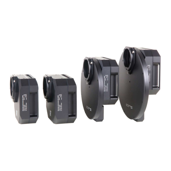
G3 Camera Overview G3 camera head is designed to be easily used with a set of accessories to fulfil various observing needs. Camera head itself is manufactured in several variants. First, there are variants differing in the cooling performance: Standard cooling ... - Page 9 Small “S” size wheel for 7 unmounted filters D50 mm or filters in 2” threaded cells. Small “M” size wheel for 7 unmounted filters D50 mm or filters in 2” threaded cells. Small “M” size wheel for 5 square filters 50×50 mm. ...
- Page 10 Figure 2: Schematic diagram of G3 camera with “S” size adapter system components...
- Page 11 Figure 3: Schematic diagram of G3 camera with “L” size adapter system components...
- Page 12 Components of G3 Camera system include: 1. G3 camera head with Internal Filter Wheel (5 positions) 2. G3 camera head with Internal Filter Wheel (5 positions) and Enhanced Cooling option 3. G3 camera head capable to control External Filter Wheel 4.
-
Page 13: Ccd Detectors And Camera Electronics
CCD Detectors and Camera Electronics G3 Mark II series of CCD cameras are manufactured with two kinds of CCD detectors: G3 cameras with OnSemi KAF Full Frame (FF) CCD architecture. Almost all Full Frame CCD detector area is exposed to light. This is why these detectors provide very high quantum efficiency. - Page 14 G3 cameras with OnSemi KAI Interline Transfer (IT) architecture. There is a shielded column of pixels just beside each column of active pixels on these detectors. The shielded columns are called Vertical registers. One pulse moves charge from exposed pixels to shielded pixels on the end of each exposure.
- Page 15 G3 camera Mark II models with Full Frame CCD detectors: Model G3-1000 G3-6300 G3-16200 G3-16200C CCD sensor KAF-1001E KAF-6303E KAF-16200 KAF-16200 Resolution 1024 × 1024 3072 × 2048 4540 × 3640 4540 × 3640 Pixel size 24 × 24 μm 9 ×...
-
Page 16: Ccd Sensor
CCD sensor Quantum efficiency (sensitivity) of CCD detectors used in G3 cameras depends on the particular camera model. Figure 6: Quantum efficiency of OnSemi CCD detectors used in G3 cameras Inherent dark current of these detectors is quite low compared to other CCD detectors, suitable for scientific applications, which results into very good signal/noise ratio. -
Page 17: Model G3-11000
Imaging area 27.6 × 18.4 mm Full well capacity Approx. 100 000 e Output node capacity Approx. 220 000 e Dark current 1 e-/s/pixel at 0°C Dark signal doubling 6.3 °C Model G3-11000 G3-11000 model uses 11 MPx CCD OnSemi KAI-11000. Resolution 4032 ×... -
Page 18: Camera Electronics
Camera Electronics 16-bit A/D converter with correlated double sampling ensures high dynamic range and CCD chip-limited readout noise. Fast USB interface ensures image download time within seconds. Maximum length of single USB cable is approx. 5 m. This length can be extended to 10 m or 15 m by using single USB hub or active USB extender cable. -
Page 19: Model G3-6300
System read noise 12 e RMS (Low noise) 15 e RMS (Preview) Download time 0.67 s (Low noise) 0.48 s (Preview) Model G3-6300 Gain 1.5 e /ADU (1×1 binning) 2.0 e /ADU (other binnings) System read noise 10 e RMS (Low noise) 12 e RMS (Preview) Download time... -
Page 20: Cooling And Power Supply
Cooling and power supply Regulated thermoelectric cooling is capable to cool down the CCD chip from 45 to 50 °C below ambient temperature, depending on the camera type. The Peltier hot side is cooled by fans. The CCD chip temperature is regulated with ±0.1 °C precision. -
Page 21: Power Supply
The camera head contains two temperature sensors – the first sensor measures directly the temperature of the CCD chip. The second one measures the temperature inside the camera shell. The cooling performance depends on the environmental conditions and also on the power supply. If the power supply voltage drops below 12 V, the maximum temperature drop is lower. - Page 22 Camera head supply 12 V DC Camera head power consumption 15 W without cooling 52 W maximum cooling Power connector 5.5/2.5 mm, center + Adapter input voltage 100-240 V AC/50-60 Hz Adapter output voltage 12 V DC/5 A Adapter maximum power 60 W Figure 8: 12 V DC/5 A power supply adapter for G3 camera Power consumption is measured on the AC side of the supplied 12 V...
- Page 23 G3 camera measures its input voltage and provides it to the control software. Input voltage is displayed in the Cooling tab of the CCD Camera control tool in the SIPS. This feature is important especially if you power the camera from batteries.
-
Page 24: Mechanical Specifications
Mechanical Specifications Compact and robust camera head measures only 154×154×65 mm (approx. 6×6×2.6 inches) for the model with standard cooling. Enhanced cooling increases camera depth by 11 mm. The head is CNC-machined from high-quality aluminum and black anodized. The head itself contains USB-B (device) connector and 12 V DC power plug, no other parts (CPU box, USB interface, etc.), except a “brick”... -
Page 25: Camera With Internal Filter Wheel
Stated back focal distance already calculates with glass permanently placed in the optical path (e.g. optical window covering the CCD cold chamber). Camera with Internal Filter Wheel Figure 9: G3 camera head front view dimensions Figure 10: G3 camera head with Internal Filter Wheel side view dimensions... -
Page 26: Enhanced Cooling Variant
Figure 11: G3 camera head with External filter wheel bottom view dimensions Enhanced cooling variant Figure 12: G3 camera head with Internal Filter Wheel and Enhanced cooling side view dimensions... -
Page 27: Camera With "S" External Filter Wheel
Camera with “S” External Filter Wheel Figure 13: G3 camera head with External filter wheel front view dimensions Figure 14: G3 camera head with External filter wheel side view dimensions... -
Page 28: Enhanced Cooling With External Filter Wheel Variant
Figure 15: G3 camera head with External filter wheel bottom view dimensions The “L” sized External Filter Wheel diameter is greater (see External Filter Wheel User's Guide), but the back focal distance of all external filter wheels is identical. Enhanced cooling with External filter wheel variant Figure 16: G3 camera head with Enhanced cooling and External filter wheel side view dimensions... -
Page 29: Optional Accessories
Optional accessories Various accessories are offered with G3 Mark II cameras to enhance functionality and help camera integration into imaging setups. Telescope adapters Various telescope and lens adapters for the G3 Mark II cameras are offered. Users can choose any adapter according to their needs and other adapters can be ordered separately. -
Page 30: Off-Axis Guider Adapter (Oag)
“M” and “L” external filter wheels are compatible with “L” adapters Small “S” size adapters: 2-inch barrel – adapter for standard 2" focusers. T-thread short – M42×0.75 inner thread adapter. T-thread with 55 mm BFD – M42×0.75 inner thread adapter, preserves 55 mm back focal distance. - Page 31 Note the G3-OAG is manufactured for “L” size adapter base, so it is compatible with “M” and “L” external filter wheels only. While G2-OAG (with M48×0.75 or M42×0.75 inner thread) for “S” size adapter base can be technically mounted to “S” size external filter wheel, the mirror is so close to optical axis, that it partially shields sensors used in G3 cameras and G2-OAG cannot be used.
-
Page 32: Attaching Camera Head To Telescope Mount
Figure 19: OAG on G3 camera with Internal filter wheel, attached to thin adapter base Attaching camera head to telescope mount G3 camera heads are equipped with two “tripod” thread (0.25”) on the top side. This thread can be used to attach 1.75 inch “dovetail bar” (Vixen standard). -
Page 33: Camera Head Color Variants
Figure 20: 1.75" bar for standard telescope mounts Camera head color variants Camera head is available in several color variants of the center plate. Visit manufacturer's web pages for current offering. Figure 21: G3 Mark II camera color variants Gx Camera Ethernet Adapter Gx Camera Ethernet Adapter allows connection of up to 4 Gx cameras of any type on the one side and 1 Gbps Ethernet on the other side. - Page 34 adapter allows access to connected Gx cameras using routable TCP/IP protocol over practically unlimited distance. Figure 22: The Gx Camera Ethernet Adapter with two connected cameras...
-
Page 35: Adjusting Of The Telescope Adapter
Adjusting of the telescope adapter All telescope/lens adapters of the Gš Mark II series of cameras can be slightly tilted. This feature is introduced to compensate for possible misalignments in perpendicularity of the telescope optical axis and sensor plane. Figure 23: Releasing of the “pushing” screw The Mark II camera telescope adapters are attached using three “pulling”... - Page 36 use only screws supplied with the adapter, using of normal M4 screws damages the adapter. Because the necessity to adjust two screws (one pushing, one pulling) at once is inconvenient, the adapter tilting mechanism is also equipped with ring-shaped spring, which pushes the adapter out of the camera body. This means the pushing screws can be released and still slight releasing of the pulling screw means the distance between the adapter and the camera body increases.
- Page 37 Only after the proper tilt is reached, the pushing screws should be slightly tightened to fix the adapter in the desired angle relative to camera head. This ensures long-time stability of the adjusted adapter. Adjustable telescope/lens adapters are attached slightly differently depending if the adapter is attached directly to the camera head (e.g.
-
Page 38: Camera Maintenance
Camera Maintenance The G3 camera is a precision optical and mechanical instrument, so it should be handled with care. Camera should be protected from moisture and dust. Always cover the telescope adapter when the camera is removed from the telescope or put the whole camera into protective plastic bag. Desiccant exchange The G3 camera cooling is designed to be resistant to humidity inside the CCD chamber. -
Page 39: Exchanging The Silica-Gel
recommended to shorten replacement interval if the silica-gel is completely transparent upon replacement. If it is still yellow-orange, it is possible to prolong the replacement interval. Figure 26: Silica-gel container is accessible from the camera back side Exchanging the silica-gel G3 Mark II cameras employ the same desiccant container like the larger G4 cameras. - Page 40 desired temperature without risking of the temperature-induced sealing damage. Figure 27: Desiccant is held inside container by perforated cap Note: New containers have a thin O-ring close to the threaded edge of the container. This O-ring plays no role in sealing the CCD cold chamber itself.
-
Page 41: Desiccant Containers For Standard Cooling And Enhanced Cooling Cameras
The sealing cap as well as the tool-less container are not supplied with the camera, they are supplied only as optional accessory. Figure 28: Optional cap, standard and tool-less container variants for both standard cooling and enhanced cooling (prolonged) cameras Desiccant containers for Standard cooling and Enhanced cooling cameras The difference between Standard and Enhanced cooling cameras is the... -
Page 42: Opening The Camera Head
Opening the camera head To open the head, unscrew the eight bolts holding camera head together. Figure 29: Filters can be exchanged after removing of the camera front cover After removing the screws carefully turn the camera head by the telescope adapter upward. -
Page 43: Changing The Telescope Adapter
Changing the Telescope Adapter All adapters of the Mark II cameras are attached using three “pulling” screws. As the adapter tilt is adjustable, another three “pushing” screws are intended to fix the adapter in place. If the adapter has to be replaced for another one, it is necessary to unscrew the three pulling screws. -
Page 44: Power Supply Fuse
Power Supply Fuse The power supply inside the camera is protected against connecting of inverted-polarity power plug or against connecting of too-high DC voltage (above 15 V) by a fuse. If such event happens and the cooling fans on the back side of the camera do not work when the camera is connected to proper power supply, return the camera to the service center for repair.
Need help?
Do you have a question about the G3 Mark II Series and is the answer not in the manual?
Questions and answers