Soyal AR-837-E Manual
Hide thumbs
Also See for AR-837-E:
- User manual (9 pages) ,
- Quick start manual (9 pages) ,
- Manual (8 pages)
Table of Contents
Advertisement
Quick Links
ACCESS & INDUSTRIAL CONTROL
Contents
AR-837-EF:Fingerprint
1
Products
Or
9DO
3DO
AR-837-E/ EE
1
Products
837-E
837-EE
Installation
A-1.Surface
A-2.Embedded
Mounted
或
Notice
1.Tubing:
The communication wires and power line should NOT be bound in the same conduit or tubing.
2.Wire selection:
Use AWG 22-24 Shielded Twist Pair to avoid star wiring, CAT 5 cable for TCP/IP connection
3.Power supply:
Don't equip reader and lock with the same power supply. The power for reader may be unstable when the lock is activating, that may cause a
malfunction in the reader.
The standard installation: Door relay and lock use the same power supply, and reader should use another independent power supply.
Connector Table (1)
CN4
Cable:
Wire Application
Wire
Lock Relay
1
Blue White (N.O.)DC24V1Amp
2
Purple White (N.C.)DC24V1Amp
Lock Relay COM
3
Door Contact
4
Exit Switch
5
Alarm Relay
6
Power
7
Thick Red
8
Thick Black DC 0V
CN5
Cable:
Wire Application
Wire
Beeper
1
2
LED
3
Door Output
4
Blue White
5
Thin Green Wiegand DAT: 0 Input
Wiegand
6
Thin Blue
WG Door Contact
7
WG Exit Switch
8
Cable:
CN6
Wire Application
Wire
1
Thick Green RS-485(B-)
RS-485 for Lift
Controller
2
Thick Blue RS-485(A+)
2
Terminal Cables
CN4
CN6
2
Terminal Cables
CN4
CN6
B.
1
Color
Description
White
(COM)DC24V1Amp
Orange
Negative Trigger Input
Purple
Negative Trigger Input
Gray
N.O./N.C. Optional (by jumper)
DC 12V
Color
Description
Pink
Beeper Output 5V/100mA, Low
Yellow
Red LED Output 5V/20mA, Max
Brown
Green LED Output 5V/20mA, Max
Transistor Output Max. 12V/100mA
(Open Collector Active Low)
Wiegand DAT: 1 Input
Orange
Negative Trigger Input
Purple
Negative Trigger Input
Color
Description
AR-837-E / EF
3
CN5
CN3
CN8
CN13
3
Tools
CN5
CN3
CN8
CN13
A-1.Surface Mounted: Use a screwdriver to screw the mounting plate
to the wall. A-2.Embedded: To dig a hole for 837-E:85mmx113mm /
837-EF:128mmx109mm; and then, use a screwdriver to screw the
mounting plate to the wall.
Pull cable ends through the access hole in the mounting plate.
Attach AR-837-E or AR-837-EF to the mounting plate and install
screws (supplied) into the holes at the bottom with the allen key.
2
Apply power. LED (green) will light up with one beep.
Cable:
CN3
Wire Application
Anti-Tamper Switch
Cable:
CN8
Wire Application
Reserved
Security trigger signal
Arming
Duress
CN13
Cable:
Wire Application
Door Bell
Screws
Water proof Strip
Screws
AR-837-E
AR-837-EE
Screws
Water proof Strip
CN7
8
CN8
3 2 1
CN3
CN13
Wire
Color
Description
1
Red
N.C.
2
Orange
COM
3
Yellow
N.O.
Wire
Color
Description
1
Red
--
2
Purple
Security trigger signal Output
3
Red White
Arming Output
4
Yellow White Duress Output
Wire
Color
Description
Transistor Output Max. 12V/100mA
1
Black White
(Open Collector Active Low)
2
Black
DC 0V
V200929
4
Optional
AR-837i
(TCP/IP Module)
AR-WG-HID
(HID RF Module)
AR-MDL-721V
(Voice Module)
4
Optional
AR-837i
(TCP/IP Module)
AR-WG-HID
(HID RF Module)
AR-MDL-721V
(Voice Module)
CN6
2
1
CN5
CN4
8
Advertisement
Table of Contents

Related Manuals for Soyal AR-837-E


Summary of Contents for Soyal AR-837-E
- Page 1 837-EF:128mmx109mm; and then, use a screwdriver to screw the mounting plate to the wall. Pull cable ends through the access hole in the mounting plate. Attach AR-837-E or AR-837-EF to the mounting plate and install 或 screws (supplied) into the holes at the bottom with the allen key.
- Page 2 LCD / Biometrics Access Controller V200929 Connector Table (2): Optional CN10 Cable: Cable: Wire Application Wire Color Description Wire Application Wire Color Description HID RF Module Orange ANT 1 Purple ANT 2 Orange White Net - TX+ Black DC 0V Orange Net - TX- DC 5V...
- Page 3 Reader WG 1 POWER POWER 12VDC 12VDC AR-837-E/EF become WG mode (28 1. When AR-837-E/EF become WG mode,it can be used with any 837-E/EF WGoutput 837-E/EF Master controllers. 2. AR-837-EF support Anti-pass-back by finger or card. ※Using Rule : Duress...
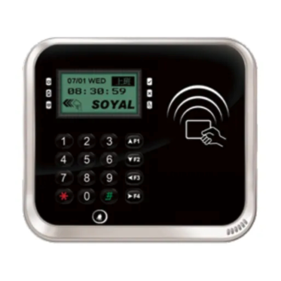
- Page 4 LCD / Biometrics Access Controller V200929 Function Description of Front Panel & Indicator System will automatically exit Programming Mode when inactivating for 30 seconds. Power LED status indicates controller’s mode and status. (Green) (Green) OK (green) – blinking constantly when operating in Programming Mode Alarm (Red) Error...
- Page 5 AR-837-E / EF V200929 ACCESS & INDUSTRIAL CONTROL Deleting Tag by Tag ID Access programming mode → Add/Delete → Delete -> ID # → Input Site Code → Input Card Code Setting up the access mode Access programming mode →...
- Page 6 LCD / Biometrics Access Controller V200929 Enable/Disable the arming status: Standby Mode Card only Card or PIN Card and PIN Open the door No open the door Input user address → Input Present the tag to reader → Input Present the tag to reader → Input →...
- Page 7 Get the upgrade software from SOYAL or our distributor and run “UdpUpdater” software Execute the software The software is within SOYAL CD or please login the SOYAL website to download Update the firmware [Please login the SOYAL website to download the new ISP Firmware.] 1.
- Page 8 LCD / Biometrics Access Controller V200929 IP Setting Open your Web Browser and input factory default IP address: http://192.168.1.127 If the IP address of AR-837 (E/EF) has be changed, we must enter the new IP address. Page menu Current Status Monitor the on-line computer Network Setting IP Setting...
Need help?
Do you have a question about the AR-837-E and is the answer not in the manual?
Questions and answers