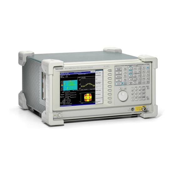
Tektronix RSA3408A Technical Reference
8 ghz real-time spectrum analyzer
performance verification and specifications
Hide thumbs
Also See for RSA3408A:
- Service manual (284 pages) ,
- User manual (80 pages) ,
- User manual (96 pages)

Related Manuals for Tektronix RSA3408A

Summary of Contents for Tektronix RSA3408A
- Page 1 Technical Reference RSA3408A 8 GHz Real-Time Spectrum Analyzer Performance Verification and Specifications 077-0007-02 www.tektronix.com...
- Page 2 Copyright © Tektronix. All rights reserved. Licensed software products are owned by Tektronix or its subsidiaries or suppliers, and are protected by national copyright laws and international treaty provisions. Tektronix products are covered by U.S. and foreign patents, issued and pending. Information in this publication supercedes that in all previously published material.
- Page 3 Tektronix, with shipping charges prepaid. Tektronix shall pay for the return of the product to Customer if the shipment is to a location within the country in which the Tektronix service center is located.
- Page 5 ........2- - 16 Digital IQ Output Connector Pin Assignment (Option 05 Only) ... 2- - 19 RSA3408A Technical Reference...
-
Page 6: Table Of Contents
....2- -15 Figure 2- -2: Digital IQ output connector pin assignment ..2- -19 RSA3408A Technical Reference... - Page 7 ....2- -19 Table 2- -24: Q OUTPUT connector pin assignment ... . . 2- -21 RSA3408A Technical Reference...
- Page 8 Table of Contents RSA3408A Technical Reference...
- Page 9 Provide Proper Ventilation. To prevent product overheating, provide proper ventilation. Do Not Operate With Suspected Failures. If you suspect there is damage to this product, have it inspected by qualified service personnel. RSA3408A Technical Reference...
- Page 10 Symbols on the Product. The following symbols may appear on the product: WARNING Protective Ground CAUTION High Voltage (Earth) Terminal Refer to Manual Certifications and Refer to the specifications section for a listing of certifications and compliances Compliances that apply to this product. RSA3408A Technical Reference...
- Page 11 The following documents relate to the use or service of the analyzer: H The RSA3408A User Manual describes how to operate your analyzer. H The RSA3408A Programmer Manual describes how to use a computer to control the analyzer through the GPIB interface.
- Page 12 Preface viii RSA3408A Technical Reference...
- Page 13 Performance Verification...
- Page 15 Tests, beginning on page 1- -9, after doing the Functional Tests and Diagnostics just referenced. Advantages: These procedures add direct checking of warranted specifica- tions. Disadvantages: They require more time to perform and suitable test equipment is required. (Refer to Equipment Required on page 1- -11.) 1- 1 RSA3408A Technical Reference...
- Page 16 The example step below is telling you to set the analyzer controls by pressing the specified key sequence. Set the RSA3408A analyzer controls: Press MODE: DEMOD > Digital Demod > Constellation. STOP. The symbol at the left is accompanied by information you must read to do the procedure properly.
- Page 17 The Functional Tests use the internal calibration signal as a test-signal source for further verifying that the analyzer functions properly. The Diagnostics use internal routines to verify that the instrument functions properly and passes the internal circuit tests. The following section provides the details. 1- 3 RSA3408A Technical Reference...
- Page 18 Press INPUT > Signal Input Port... > Cal100M. The spectrum of the calibration signal appears. d. Check that “INPUT: CAL” and “FREE RUN” are displayed in the status indicator at the upper right of the screen (see Figure 1- -1). 1- 4 RSA3408A Technical Reference...
-
Page 19: Figure 1- 1: Spectrum Of The Calibration Signal (100 Mhz, - 20 Dbm)
Press the SPAN key on the front panel. b. Confirm that the span is 36 MHz and the RBW is 100 kHz in the setup display on the upper part of the screen (see Figure 1- -2). 1- 5 RSA3408A Technical Reference... -
Page 20: Figure 1- 2: Setup Display
Figure 1- -3. e. Using the numeric keypad, set the reference level back to 0 dBm. (Press 0 > ENTER, in that order, on the keypad.) 1- 6 RSA3408A Technical Reference... -
Page 21: Figure 1- 3: Reference Level Setting And A/D Overflow Indicator
Figure 1- 4: Spectrogram display b. Press the RUN/STOP key on the front panel to stop data acquisition. Confirm that the trace display freezes and PAUSE is displayed in the status indicator at the top right of the screen. 1- 7 RSA3408A Technical Reference... -
Page 22: Figure 1- 5: Diagnostic Screen
You can press the All side key to run all the tests. 5. Check the result shown in the lower left view (“Pass” or “Fail”). The process is graphically displayed on the upper views. Figure 1- 5: Diagnostic screen 1- 8 RSA3408A Technical Reference... - Page 23 Performance Tests This section contains procedures for checking that the RSA3408A 8 GHz Real-Time Spectrum Analyzer performs as warranted. The procedures are arranged in four logical groupings: H Frequency Checks H Noise Sideband Checks H Amplitude Checks H Spurious Response Checks They check all the characteristics that are designated as checked in Chapter 2, Specification.
- Page 24 +20 _C and +30 _C, must have been operating for a warm-up period of at least 20 minutes, and must be operating at an ambient tempera- ture of between +10 _C and +40 _C. 1- 10 RSA3408A Technical Reference...
-
Page 25: Table 1- 3: Test Equipment
50 Ω, 36 in, male N to male SMA Signal interconnection (Three required) connectors 12. Terminator Impedance: 50 Ω; connectors: female Tektronix part number Signal termination for check- BNC input, male BNC output 011-0049-01 ing frequency accuracy 1- 11 RSA3408A Technical Reference... - Page 26 - -10 dBm c. Hook up the signal generator: Connect the generator output through a 50 Ω N-N coaxial cable to the analyzer INPUT. See the following figure. RSA3408A Signal generator Output 50 Ω N-N coaxial cable 1- 12 RSA3408A Technical Reference...
- Page 27 H With the Center Freq side key, set the frequency to 2 GHz using the numeric keypad. c. Measure peak frequency: H Press the PEAK key to place the marker on the peak signal. H Read the marker readout. Confirm that the value is 2 GHz 1.4 kHz. 1- 13 RSA3408A Technical Reference...
- Page 28 H Press the PEAK key to place the marker on the peak signal. H Read the marker readout. Confirm that the value is 7 GHz 2.4 kHz. 6. Disconnect the test equipment: Disconnect the cable at the analyzer input. 1- 14 RSA3408A Technical Reference...
- Page 29 ....2. Check the frequency: Check that the frequency counter reads 10 MHz 2.0 Hz. 3. Disconnect the hookup: Disconnect the cable at REF OUT. 1- 15 RSA3408A Technical Reference...
- Page 30 ....d. Hook up the signal generator: Connect the generator output through a 50 Ω N-N coaxial cable to the analyzer INPUT. See the following figure. 1- 16 RSA3408A Technical Reference...
- Page 31 H Press the Noise Bandwidth side key and set the value to 1 kHz using the general purpose knob. c. Check against limits: Read the phase noise (C/No) at the bottom of the screen. Confirm that the value is 110 dB/Hz or more. 1- 17 RSA3408A Technical Reference...
- Page 32 Check against limits: Read the phase noise (C/No) at the bottom of the screen. Confirm the value is 132 dB/Hz or more. 5. Disconnect the test equipment: Disconnect the cable at the analyzer input. 1- 18 RSA3408A Technical Reference...
- Page 33 See Figure 1- -6 on page 1- -20. e. Turn on POWER REF and execute the calibration. Disconnect the RF input of the power sensor from the reference output of the power meter. 1- 19 RSA3408A Technical Reference...
-
Page 34: Figure 1- 6: Hookup For Calibrating The Power Sensor
....10 MHz d. Adjust the output level of the signal generator so that the power meter reads - -10 dBm 0.05 dBm. e. Disconnect the cable from the power sensor input. 1- 20 RSA3408A Technical Reference... -
Page 35: Figure 1- 8: Hookup For Checking The Absolute Amplitude Accuracy
Performance Tests 3. Prepare for the test: a. Hook up the instruments: Connect the signal generator output through a 50 Ω N-N coaxial cable to the RSA3408A INPUT. See Figure 1- -8. RSA3408A Signal generator Output 50 Ω N-N coaxial cable Figure 1- 8: Hookup for checking the absolute amplitude accuracy b. - Page 36 Hook up the instruments: Connect the signal generator output through a 50 Ω N-N coaxial cable to the RSA3408A INPUT. See Figure 1- -8 on page 1- -21. b. Modify the analyzer controls: H Press the FREQUENCY/CHANNEL key on the front panel.
- Page 37 Press the PEAK key on the front panel to place the marker on the peak. b. Check that the marker readout is within - -20 dBm 0.5 dB. 9. Disconnect the test equipment: Disconnect the cable at the analyzer input. 1- 23 RSA3408A Technical Reference...
- Page 38 INPUT. See the following figure. RSA3408A Signal generator Output 50 Ω N-N coaxial cable c. Initialize the analyzer: H Press the SYSTEM key on the front panel. H Press the Reset All to Factory Defaults side key. 1- 24 RSA3408A Technical Reference...
- Page 39 Repeat substeps a through d for attenuation from 5 to 30 dB in 5 dB steps. 4. Modify the generator controls: Amplitude ....- -5 dBm 1- 25 RSA3408A Technical Reference...
- Page 40 - - P ) is within 0.2 dB. e. Repeat substeps a through d for attenuation from 35 to 55 dB in 5 dB steps. 8. Disconnect the test equipment: Disconnect the cable at the analyzer input. 1- 26 RSA3408A Technical Reference...
- Page 41 ....100 MHz Level ....+10 dBm 1- 27 RSA3408A Technical Reference...
- Page 42 ... . 10 dB ....Auto 1- 28 RSA3408A Technical Reference...
- Page 43 Signal generator amplitude Reference power - - 40 dBm b. Disconnect the cable from the spectrum analyzer. 7. Modify the hookup: a. Connect the signal generator output to the RSA3408A analyzer input. See the following figure. RSA3408A Signal generator Output 50 Ω...
-
Page 44: Table 1- 4: Level Linearity Test Result
Performance Tests c. Modify the RSA3408A analyzer controls: Center frequency ..100 MHz Span .... - Page 45 See the following figure. RSA3408A Signal generator Output N-SMA cable Signal generator Power combiner N-SMA cable Output b. Connect the power combiner output through a 50 Ω N-SMA coaxial cable to the analyzer INPUT. 1- 31 RSA3408A Technical Reference...
- Page 46 H Press TRACE/AVG > Trace 1 Type... > Average. H Press the Number Of Averages side key and set the value to 50 using the general purpose knob. H Press the MARKER SETUP key. H Press the Markers side key to select Delta. 1- 32 RSA3408A Technical Reference...
- Page 47 3. Check against limits: Confirm that the lowest value meets the requirement of - -78 dBc. 4. Disconnect the test equipment: Disconnect the cable at the analyzer input. 1- 33 RSA3408A Technical Reference...
- Page 48 H Press the RBW/FFT key on the front panel. H Press the RBW/FFT side key to select Man. H With the RBW side key, set the value to 10 kHz using the general purpose knob. 1- 34 RSA3408A Technical Reference...
- Page 49 H With the Center Freq side key, set the frequency to 3 GHz using the general purpose knob. b. Check against limits: Read the measurement result of Density at the bottom of the screen. Check that the value is - -150 dBm/Hz or less. 1- 35 RSA3408A Technical Reference...
- Page 50 H With the Center Freq side key, set the frequency to 7 GHz using the general purpose knob. b. Check against limits: Read the measurement result of Density at the bottom of the screen. Check that the value is - -142 dBm/Hz or less. 1- 36 RSA3408A Technical Reference...
- Page 51 H With the RBW side key, set the RBW to 100 kHz using the general purpose knob. H Press TRACE/AVG > Trace 1 Type... > Average. H Press the Number Of Averages side key and set the value to 50 using the general purpose knob. 1- 37 RSA3408A Technical Reference...
- Page 52 H Press the Number Of Line key to select 1. H Press the Line1 side key and set the value to - -90 dBm using the numeric keypad. c. Check against limits: Confirm that the residual signal level is - -90 dBm or less. 1- 38 RSA3408A Technical Reference...
- Page 53 Press the PEAK key to place the marker at the peak on the noise floor. c. Check against limits: Read the marker readout. Confirm that the residual signal level is - -85 dBm or less within the whole bandwidth. 1- 39 RSA3408A Technical Reference...
- Page 54 ....- -5 dBm d. Hook up the signal generator: Connect the generator output through a 50 Ω N-N coaxial cable to the analyzer INPUT. See the following figure. 1- 40 RSA3408A Technical Reference...
- Page 55 H Press the PEAK key to place Marker 2 on the peak signal. H Read the delta marker readout (Δ1- -2) on the screen. Check that the components other than the carrier meet the requirement as shown in Table 1- -5 (initially - -73 dBc). 1- 41 RSA3408A Technical Reference...
-
Page 56: Table 1- 5: Spurious Measurement
25 MHz - - 73 dBc 2 GHz - - 73 dBc 5 GHz - - 70 dBc 7 GHz - - 70 dBc 3. Disconnect the test equipment: Disconnect the cable at the analyzer input. 1- 42 RSA3408A Technical Reference... - Page 57 Performance Tests Test Record Photocopy the following test record pages and use them to record the perfor- mance test results for your analyzer. 1- 43 RSA3408A Technical Reference...
- Page 58 Performance Tests RSA3408A Test Record Serial Number: Certificate Number: Calibration Date: Technician: Frequency readout test Frequency Low limit Test result High limit 10 MHz 9,999 kHz 10,001 kHz 2 GHz 1,999,998.6 kHz 2,000,001.4 kHz 5 GHz 4,999,998.0 kHz 5,000,002.0 kHz 7 GHz 6,999,997.6 kHz...
- Page 59 - - 40 dBm - - 0.2 dB +0.2 dB order intermodulation distortion test Low limit Test result High limit order intermodulation distortion - - 78 dBc +5 dBm reference level, 2 GHz center frequency 1- 45 RSA3408A Technical Reference...
- Page 60 - - 85 dBm Spurious response test Frequency Low limit Test result High limit 25 MHz - - 73 dBc 2 GHz - - 73 dBc 5 GHz - - 70 dBc 7 GHz - - 70 dBc 1- 46 RSA3408A Technical Reference...
- Page 61 Specifications...
- Page 63 Specifications This section contains the RSA3408A 8 GHz Real-Time Spectrum Analyzer specifications. All specifications are guaranteed unless labeled Typical. Typical specifications are provided for your convenience. NOTE. In these tables, those warranted characteristics that are checked in the Performance Verification appear with the n symbol in the Characteristics column.
- Page 64 (within one year after calibration) Total frequency error Reference output level >0 dBm External reference input 10 MHz, - - 10 to +6 dBm. Spurious level must be <- - 80 dBc within 100 kHz offset. 2- 2 RSA3408A Technical Reference...
-
Page 65: Table 2- 2: Noise Sideband
- - 112 dBc/Hz 30 kHz - - 115 dBc/Hz 100 kHz - - 135 dBc/Hz 1 MHz - - 140 dBc/Hz 5 MHz - - 140 dBc/Hz 7 MHz - - 140 dBc/Hz 10 MHz 2- 3 RSA3408A Technical Reference... - Page 66 (Option 03 IQ input) Maximum input power +30 dBm (RF1 to 3, RF attenuation≥10 dB) Input attenuator RF/Baseband attenuator 0 to 55 dB (5 dB step) I/Q attenuator (Option 03) 0 to 35 dB (5 dB step) 2- 4 RSA3408A Technical Reference...
-
Page 67: Table 2- 4: Amplitude
(20 to 30 _C) ±0.2 dB (at 100 MHz) Input attenuator setting uncertainty ±0.2 dB (0 to - - 50 dBfs); ±0.12 dB (0 to - - 50 dBfs, Typical) Level linearity in display range 2- 5 RSA3408A Technical Reference... -
Page 68: Table 2- 5: Spurious Response
- - 70 dBc (Signal frequency = 5 GHz, Signal level = - - 5 dBm) RF3, 7 GHz - - 70 dBc (Signal frequency = 7 GHz, Signal level = - - 5 dBm) 2- 6 RSA3408A Technical Reference... -
Page 69: Table 2- 6: Acquisition
(Real Time S/A, Demod, and Time modes) Maximum: 16,384,000 samples (Standard); 65,536,000 samples (Option 02) Acquisition length setting resolution 1024 samples (Real Time S/A, Demod, and Time modes) Acquisition memory size Standard: 64 MB; Option 02: 256 MB 2- 7 RSA3408A Technical Reference... -
Page 70: Table 2- 7: Trigger
- - 1.5 to +1.5 V settable Setting Resolution 0.1 V Input impedance >2 kΩ Trigger output voltage High: >2.0 V, Low: <0.4 V (output current <1 mA) Trigger marker position timing uncertainty ±2 sample points (Power/External trigger) 2- 8 RSA3408A Technical Reference... -
Page 71: Table 2- 8: Rbw (Resolution Bandwidth)
Table 2- 9: Trace and display line Characteristics Description Number of traces Trace type Normal, Average, Max Hold, Min Hold Display detector Positive peak, Negative peak, and Positive-Negative peak Display line Horizontal line 1 and 2, Vertical line 1 and 2 2- 9 RSA3408A Technical Reference... -
Page 72: Table 2- 10: Display
±2% (- - 10 dBfs input at center, 10 to 60% modulation depth) PM demodulation ±3° (- - 10 dBfs input at center) FM demodulation ±1% of span (- - 10 dBfs input at center) 2- 10 RSA3408A Technical Reference... -
Page 73: Table 2- 13: Pulse Measurement
Binary, Octal, Hexadecimal AM/AM Measured amplitude versus Reference amplitude 1 dB compression measurement AM/PM Phase error versus Reference amplitude CCDF Probability of exceed versus Power level, Crest factor measurement Probability of occurrence versus Power level 2- 11 RSA3408A Technical Reference... - Page 74 0.6% 100 kHz 0.6% 1 MHz 0.6% 4 MHz 0.9% 10 MHz 1.8% 20 MHz Center frequency = 5 GHz 0.7% 100 kHz 0.7% 1 MHz 0.9% 4 MHz 1.6% 10 MHz 2.4% 20 MHz 2- 12 RSA3408A Technical Reference...
-
Page 75: Table 2- 15: Aclr Measurement (Option 27)
Residual EVM (Typical) IEEE 802.11a/g, 54 Mbps OFDM ≤- - 44 dB (center frequency = 2.447 GHz) ≤- - 42 dB (center frequency = 5.5 GHz) IEEE 802.11b, 11 Mbps CCK ≤0.7% (center frequency = 2.447 GHz) 2- 13 RSA3408A Technical Reference... -
Page 76: Table 2- 17: Controller
>5 ns (clock rising edge to data transition). See Figure 2- - 1. Flatness of output data before correction Amplitude +1/- - 5 dB (36 MHz span); +1/- - 2 dB (20 MHz span) Phase ±100_ (36 MHz span); ±15_ (20 MHz span) 2- 14 RSA3408A Technical Reference... -
Page 77: Figure 2- 1: Definition Of The Setup And Hold Time
5 A rms at 50 Hz (90 V line with 5% clipping) Surge current Maximum 52 A peak (25 _C) for ≤5 line cycles after the product has been turned off for at least 30 s. 2- 15 RSA3408A Technical Reference... -
Page 78: Table 2- 20: Physical Characteristics
(20 G), half-sine, 11 ms duration Three shocks in each direction along each major axis, total of 18 shocks Cooling clearance Bottom 20 mm (0.79 in) Both sides 50 mm (1.97 in) Rear 50 mm (1.97 in) 2- 16 RSA3408A Technical Reference... -
Page 79: Table 2- 22: Certifications And Compliances
IEC61010-1 Safety requirements for electrical equipment for measurement, control, and laboratory use. Emissions which exceed the levels required by this standard may occur when this equipment is connected to a test object. 2- 17 RSA3408A Technical Reference... - Page 80 Pollution Degree 2 (as defined in IEC61010-1). Note: Rated for indoor use only. Safety Certification Compliance Equipment Type Test and measuring Safety Class Class I (as defined in IEC61010-1) - - grounded product Operating Temperature Range +5 to +40 _C 2- 18 RSA3408A Technical Reference...
-
Page 81: Figure 2- 2: Digital Iq Output Connector Pin Assignment
I output data (bit 2), LVDS EXT_I2+ EXT_I3- - I output data (bit 3), LVDS EXT_I3+ Ground EXT_I4- - I output data (bit 4), LVDS EXT_I4+ EXT_I5- - I output data (bit 5), LVDS EXT_I5+ 2- 19 RSA3408A Technical Reference... - Page 82 I output data (bit 13), LVDS EXT_I13+ EXT_I14- - I output data (bit 14), LVDS EXT_I14+ EXT_I15- - I output data (bit 15), LVDS EXT_I15+ Ground EXT_IQ_DAV- - Not used EXT_IQ_DAV+ EXT_IQ_CLK- - IQ output clock, LVDS EXT_IQ_CLK+ 2- 20 RSA3408A Technical Reference...
-
Page 83: Table 2- 24: Q Output Connector Pin Assignment
Q output data (bit 7), LVDS EXT_Q7+ Ground EXT_Q8- - Q output data (bit 8), LVDS EXT_Q8+ EXT_Q9- - Q output data (bit 9), LVDS EXT_Q9+ EXT_Q10- - Q output data (bit 10), LVDS EXT_Q10+ 2- 21 RSA3408A Technical Reference... - Page 84 Q output data (bit 12), LVDS EXT_Q12+ EXT_Q13- - Q output data (bit 13), LVDS EXT_Q13+ EXT_Q14- - Q output data (bit 14), LVDS EXT_Q14+ EXT_Q15- - Q output data (bit 15), LVDS EXT_Q15+ Ground Not used 2- 22 RSA3408A Technical Reference...
Need help?
Do you have a question about the RSA3408A and is the answer not in the manual?
Questions and answers