Table of Contents
Advertisement
Quick Links
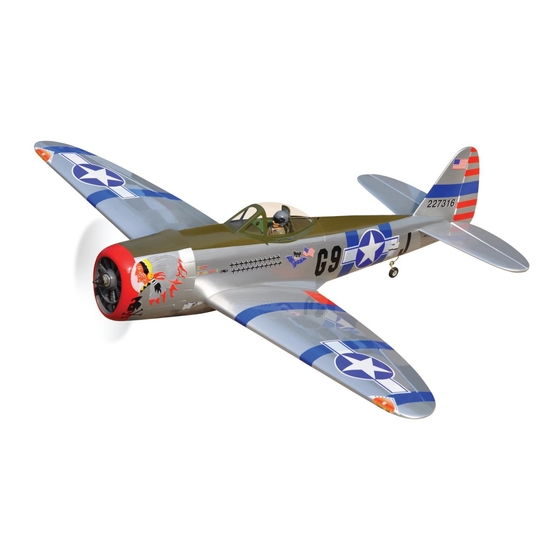
P47-THUNDERBOLT
ALL BALSA - PLY WOOD CONSTRUCTION.
COVERED WITH ORACOVER.
95% ALMOST READY TO FLY
SPECIFICATION
- Wingspan: 1,620mm (64in).
- Length: 1,340mm (53in).
- Weight: 4.4kg (9.68lbs).
- Wing area: 46.1dm
- Wing loading: 95.4g/dm
- Wing type: Naca Airfoil.
- Gear type: Air retract gear
with oleo struts (included).
- Servo mount: 42mm x 21mm.
Parts listing required (not included):
- Radio: 06 channels.
Instruction Manual Book
.
2
.
2
Item code: BH36-B.
- Servo: 08 servos.
- Engine: 61-75
2 strokes; 15cc Gas.
- Motor: Brushless outrunner 1200-2200W, 650KV.
- Propeller: Suit with your engine.
Recommended Motor and Battery set up
(not included):
- Motor: RIMFIRE.60.
- Lipo cell: 6 cells 4,000-5,000mAh.
- ESC: 80A.
- Receiver battery: 6V/ 1200-2000mAh NiMH.
Made in Vietnam.
Advertisement
Table of Contents

Subscribe to Our Youtube Channel
Related Manuals for Black Horse Model BH36-B


Summary of Contents for Black Horse Model BH36-B
- Page 1 Instruction Manual Book Item code: BH36-B. P47-THUNDERBOLT ALL BALSA - PLY WOOD CONSTRUCTION. COVERED WITH ORACOVER. 95% ALMOST READY TO FLY SPECIFICATION - Servo: 08 servos. - Wingspan: 1,620mm (64in). - Engine: 61-75 2 strokes; 15cc Gas. - Length: 1,340mm (53in).
-
Page 2: Tools And Supplies Needed
P47-THUNDERBOLT. Item code: BH36-B. Instruction Manual This instruction manual is designed to help you build a great flying aeroplane. Please read this manual thoroughly before starting assembly of your P47-THUNDERBOLT. Use the parts listing below to identify all parts. WARNINg Please be aware that this aeroplane is not a toy and if assembled or used incorrectly it is capable of causing injury to people or property. -
Page 3: Safety Precaution
P47-THUNDERBOLT. Item code: BH36-B. Instruction Manual Caution: This model is not a toy! This model is highly pre-fabricated and can be built in If you are a beginner to this type of powered model, a very short time. However, the work which you have to please ask an experienced model flyer for help and carry out is important and must be done carefully. - Page 4 P47-THUNDERBOLT. Item code: BH36-B. Instruction Manual REPLACEMENT SMALL PARTS 3x15mm 4x30mm 5x35mm 3x6mm 3x4mm 3x12mm 4x70mm 1. Door mounting wheel. 2. Retract main gear. 3. Wheels. 3x12mm 4x20mm 4. Tail gear set. 5. Plastic - engine mount. 2x10mm 6. Wood - motor mount.
-
Page 5: Installing The Aileron Servos
P47-THUNDERBOLT. Item code: BH36-B. Instruction Manual 2. INSTALLINg THE AILERON SERVOS Electric wire 1) Install the rubber grommets and brass eyelets on to the aileron servos. 2) Using a modeling knife, remove the covering from over the pre-cut servo arm exit hole on the aileron servo tray / hatch. -
Page 6: Installing The Aileron Linkages
P47-THUNDERBOLT. Item code: BH36-B. Instruction Manual Flap install as same as the way of aileron. Repeat 3) Repeat the procedure to install the control horn step #1 - #4 on the part I (page 4,5) to install the flap. -
Page 7: Installing The Engine Mount
P47-THUNDERBOLT. Item code: BH36-B. Instruction Manual Secure the air retract to the wing. Top side Bottom side 3 x 15mm Drill a hole Secure 3mm diameter 3x6mm Secure Install and secure the wheel. Collar Secure 5x35mm Repeat the procedure to install the opposite gear. -
Page 8: Option 1: Electric Motor
P47-THUNDERBOLT. Item code: BH36-B. Instruction Manual OPTION 1: ELECTRIC MOTOR OPTION 2: ENgINE MOUNT 4x30mm 4x70mm 4x20mm Locate the long piece of wire used for the throttle pushrod. One end of the wire has been pre-bend in to a “Z” bend at the factory. This “Z” bend should be inserted into the throttle arm of the engine when the engine is fitted onto the engine mount. -
Page 9: Installing The Fuselage Servos
P47-THUNDERBOLT. Item code: BH36-B. Instruction Manual from the rear of the tank and move freely inside the lines have not become kinked inside the fuel tank tank). Connect one end of the line to the weighted compartment. Air should flow through easily. -
Page 10: Installing Horizontal Stabilizer
P47-THUNDERBOLT. Item code: BH36-B. Instruction Manual of the cowl opening. Hold the cowl firmly in place using Pushrod wire pieces of masking tape. 3) Slide the cowl back over the engine and secure it in place using four wood screws. See picture below. - Page 11 P47-THUNDERBOLT. Item code: BH36-B. Instruction Manual 5) With the horizontal stabilizer correctly aligned, mark the shape of the fuselage on the top and the bottom of the tail plane using a water soluble / non permanent felt-tip pen. Trim the covering from the tail slots.
- Page 12 P47-THUNDERBOLT. Item code: BH36-B. Instruction Manual 2. ELEVATOR PUSHROD INSTALLATION Bottom side. Drill a hole 1.5 mm Elevator pushrod Elevator control horn Silicone Tube M2 Lock nut When you are sure that everything is aligned correctly, mix up a generous amount of 30 minute ...
- Page 13 P47-THUNDERBOLT. Item code: BH36-B. Instruction Manual 3 x 12mm Push in Rudder pushrod 1. RUDDER CONTROL HORN INSTALLATION 2. Secure the tail wheel bracket in place using three 3mm x 12mm wood screws. Be careful not to Rudder control horn install as same as method of overtighten the screws.
- Page 14 P47-THUNDERBOLT. Item code: BH36-B. Instruction Manual Please see pictures below. Rudder pushrod Valve control 3 way conector Connector Valve one way Rudder control horn M2 Lock nut Air line sets Rudder servo Air supply Rudder pushrod Air tank Snap keeper...
- Page 15 P47-THUNDERBOLT. Item code: BH36-B. Instruction Manual...
-
Page 16: Wing Attachment
P47-THUNDERBOLT. Item code: BH36-B. Instruction Manual *** Test fit the aluminium tube dihedral brace into each X. INSTALLINg THE SWITCH, wing haft. The brace should slide in easily. If not, use RECEIVER AND BATTERY 220 grit sand around the edges and ends of the brace until it fits properly. - Page 17 P47-THUNDERBOLT. Item code: BH36-B. Instruction Manual Open and Close Adhesive tape. A+B Epoxy glue. BALANCINg 1) It is critical that your airplane be balanced cor- rectly. Improper balance will cause your plane to lose control and crash. THE CENTER OF GRAVITY IS LOCATED 95MM BACK FROM THE LEADING EDGE OF THE WING.
-
Page 18: Pre-Flight Check
P47-THUNDERBOLT. Item code: BH36-B. Instruction Manual Moving the balance aft makes the model more agile with a lighter and snappier ”feel”. In any case, please 15mm start at the location we recommend. 15mm With the wing attached to the fuselage, all parts of the... - Page 19 P47-THUNDERBOLT. Item code: BH36-B. Instruction Manual I/C FLINgT WARNINgS Always operate in open areas, away adjust the engine from ALWAYS from factories, hospitals, schools, NEVER fly near power lines, behind the propeller, and do not buildings and houses etc. NEVER...
Need help?
Do you have a question about the BH36-B and is the answer not in the manual?
Questions and answers