Table of Contents
Advertisement
Quick Links
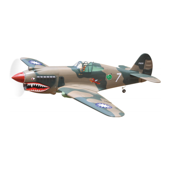
P-40C TOMAHAWK
INCLUDING AIR RETRACT.
AIR UP, AIR DOWN, TURN AND TWIST OLEO STRUTS LANDING GEAR.
ALL BALSA - PLY WOOD CONSTRUCTION.
COVERED IN A HEAT - SHRINK FILM WITH PRINTED.
95% ALMOST READY TO FLY
SPECIFICATION
- Wingspan: 1,643mm (64.69in).
- Length: 1,405mm (45.51in).
- Weight: 4.6-4.8 kg (10.12- 10.56 lbs).
- Wing area: 46.7dm
- Wing loading: 98.5 - 102.8 g/dm
- Wing type: Naca Airfoil.
- Gear type: Air retract gear
CNC Suspension Metal Struts (included).
- Spinner: 95mm.
- Servo mount: 42mm x 21mm.
Instruction Manual Book
.
2
.
2
Item code: BH56-A.
Parts listing required (not included):
- Radio: 06 channels.
- Servo: 08 servos.
- Engine: 75 cu.in 02 stroke; 15cc Gas.
- Motor: Brushless outrunner 1200-2200W, 650KV.
- Propeller: Suit with your engine.
Recommended Motor and Battery set up
(not included):
- Motor: RIMFIRE.60.
- Lipo cell: 6 cells 4,000-5,000mAh.
- Receiver battery: 6V/ 1200-2000mAh NiMH.
- ESC: 80A.
Made in Vietnam.
Advertisement
Table of Contents

Subscribe to Our Youtube Channel
Related Manuals for Black Horse Model P-40C


Summary of Contents for Black Horse Model P-40C
- Page 1 Instruction Manual Book Item code: BH56-A. P-40C TOMAHAWK INCLUDING AIR RETRACT. AIR UP, AIR DOWN, TURN AND TWIST OLEO STRUTS LANDING GEAR. ALL BALSA - PLY WOOD CONSTRUCTION. COVERED IN A HEAT - SHRINK FILM WITH PRINTED. 95% ALMOST READY TO FLY...
-
Page 2: Tools And Supplies Needed
P-40C TOMAHAWK Item code: BH56-A. Instruction Manual This instruction manual is designed to help you build a great flying aeroplane. Please read this manual thoroughly P-40C TOMAHAWK before starting assembly of your . Use the parts listing below to identify all parts. -
Page 3: Safety Precaution
P-40C TOMAHAWK Item code: BH56-A. Instruction Manual Caution: This model is not a toy! This model is highly pre-fabricated and can be built in If you are a beginner to this type of powered model, a very short time. However, the work which you have to please ask an experienced model flyer for help and carry out is important and must be done carefully. - Page 4 P-40C TOMAHAWK Item code: BH56-A. Instruction Manual REPLACEMENT SMALL PARTS 3x15 mm 4x30mm 5x35mm 3x12mm 4x70mm 1. Retract main gear. 2. Wheels. 3x12mm 3. Tail gear set. 4x20mm 4. Plastic - engine mount. 5. Wood - motor mount. 2x10mm 6. Spinner.
-
Page 5: Installing The Aileron Servos
P-40C TOMAHAWK Item code: BH56-A. Instruction Manual 2. INSTALLING THE AILERON SERVOS Electric wire 1) Install the rubber grommets and brass eyelets on to the aileron servos. 2) Using a modeling knife, remove the covering from over the pre-cut servo arm exit hole on the aileron servo tray / hatch. -
Page 6: Installing The Aileron Linkages
P-40C TOMAHAWK Item code: BH56-A. Instruction Manual Flap install as same as the way of aileron. Repeat 3) Repeat the procedure to install the control horn step #1 - #4 on the part I (page 4,5) to install the flap. - Page 7 P-40C TOMAHAWK Item code: BH56-A. Instruction Manual Place the retract to the wing and pull out the air tube through the wing section. Wheel well Glue the plastic part h Secure the air retract to the wing. 3x15 mm C/A glue...
-
Page 8: Installing The Engine Mount
P-40C TOMAHAWK Item code: BH56-A. Instruction Manual IV. INSTALLING THE ENGINE MOUNT There are two options: OPTION 2: ENGINE MOUNT 1. Electric motor 2. Engine mount. OPTION 1: ELECTRIC MOTOR 4x30mm 4x70mm 4x20mm Locate the long piece of wire used for the throttle pushrod. - Page 9 P-40C TOMAHAWK Item code: BH56-A. Instruction Manual 5) Test fit the stopper assembly into the tank. It may 125mm be necessary to remove some of the flashing around the tank opening using a modeling knife. If flashing is present, make sure none of it falls into the tank.
-
Page 10: Installing The Fuselage Servos
P-40C TOMAHAWK Item code: BH56-A. Instruction Manual 2.INSTALLING THE FUSELAGE SERVOS Secure Throttle pushrod 1) Install the rubber grommets and brass collets into the elevator, rudder and throttle servos. Test fit the servos into the servo tray. Trim the tray if neces- Throttle servo sary to fit your servos. - Page 11 P-40C TOMAHAWK Item code: BH56-A. Instruction Manual of the cowl opening. Hold the cowl firmly in place using pieces of masking tape. 3) Slide the cowl back over the engine and secure Trim the covering it in place using four wood screws. See picture below.
- Page 12 P-40C TOMAHAWK Item code: BH56-A. Instruction Manual 5) With the horizontal stabilizer correctly aligned, mark the shape of the fuselage on the top and the bottom of the tail plane using a water soluble / non permanent felt-tip pen.
- Page 13 P-40C TOMAHAWK Item code: BH56-A. Instruction Manual 2. ELEVATOR PUSHROD INSTALLATION Bottom side. Elevator pushrod Silicone Tube M2 Lock nut Push in 1) Using pliers, carefully make a 90 degree bend down at the mark made. Cut off the excess wire, leaving about 6mm beyond the blend.
- Page 14 P-40C TOMAHAWK Item code: BH56-A. Instruction Manual Rudder pushrod 3 x 12mm Rudder control horn M2 Lock nut Rudder servo Rudder pushrod Snap keeper Flaslink Servo arm Pushrod wire Rudder pushrod Secure Rudder pushrod 2. Secure the tail wheel bracket in place using three 3mm x 12mm wood screws.
- Page 15 P-40C TOMAHAWK Item code: BH56-A. Instruction Manual...
-
Page 16: Wing Attachment
P-40C TOMAHAWK Item code: BH56-A. Instruction Manual X. INSTALLING THE SWITCH, Valve control 3 way conector RECEIVER AND BATTERY 1) Cut out the switch hole using a modeling knife. Connector Valve one way Use a 2mm drill bit and drill out the two mounting holes through the fuselage side. - Page 17 P-40C TOMAHAWK Item code: BH56-A. Instruction Manual Locate the aluminium wing dihedral brace. XII. INSTALLING COCKPIT FUSELAGE, PROPELLERS Aluminium tube. 19mm. Please see pictures below. 436mm *** Test fit the aluminium tube dihedral brace into each wing haft. The brace should slide in easily. If not, use 220 grit sand around the edges and ends of the brace until it fits properly.
-
Page 18: Installing The Spinner
P-40C TOMAHAWK Item code: BH56-A. Instruction Manual Installing the fuselage hatch as same as picture below. BALANCING Open and 1) It is critical that your airplane be balanced cor- Close rectly. Improper balance will cause your plane to lose control and crash. -
Page 19: Pre-Flight Check
6) Properly balance the propeller. We wish you many safe and enjoyable flights CONTROL THROWS with your P-40C TOMAHAWK 1) We highly recommend setting up a plane using the control throws listed. 2) The control throws should be measured at the widest point of each control surface. - Page 20 P-40C TOMAHAWK Item code: BH56-A. Instruction Manual I/C FLINGT WARNINGS Always operate in open areas, away adjust the engine from ALWAYS from factories, hospitals, schools, NEVER fly near power lines, behind the propeller, and do not buildings and houses etc. NEVER...
Need help?
Do you have a question about the P-40C and is the answer not in the manual?
Questions and answers