Table of Contents
Advertisement
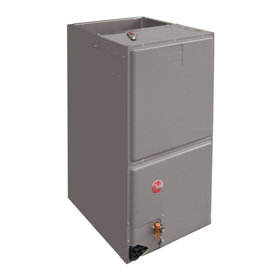
INSTALLATION INSTRUCTIONS
FEATURING INDUSTRY STANDARD R-410A REFRIGERANT:
(-)H1V Premium Efficiency Single Stage with Aluminum Coil
(-)H2V Premium Efficiency Two Stage Comfort Control
(-)H2V
with Aluminum Coil
WARNING
LWARNING
These instructions are intended as an aid to qualified licensed
service personnel for proper installation, adjustment and
operation of this unit. Read these instructions thoroughly before
attempting installation or operation. Failure to follow these
instructions may result in improper installation, adjustment,
service or maintenance possibly resulting in fire, electrical
shock, property damage, personal injury or death.
AIR HANDLERS
2
System™
ISO 9001:2008
92-20521-65-02
SUPERSEDES 92-20521-65-01
r e f r i g e r a n t
Advertisement
Table of Contents

Related Manuals for Rheem RH1V2417STANJA


Summary of Contents for Rheem RH1V2417STANJA
- Page 1 INSTALLATION INSTRUCTIONS AIR HANDLERS FEATURING INDUSTRY STANDARD R-410A REFRIGERANT: r e f r i g e r a n t (-)H1V Premium Efficiency Single Stage with Aluminum Coil (-)H2V Premium Efficiency Two Stage Comfort Control System™ (-)H2V with Aluminum Coil WARNING LWARNING These instructions are intended as an aid to qualified licensed...
-
Page 2: Table Of Contents
CONTENTS 1.0 SAFETY INFORMATION ..........3 2.0 GENERAL INFORMATION. -
Page 3: Safety Information
1.0 SAFETY INFORMATION WARNING Duct leaks can create an unbalanced system and draw pollutants such as dirt, dust, fumes and odors into the home causing property damage. Fumes and odors from toxic, volatile or flammable chemicals, as well as automobile exhaust and carbon monoxide (CO), can be drawn into the living space through leaking ducts and unbalanced duct systems causing personal injury or death (see Figure 1). - Page 4 WARNING PROPOSITION 65: This appliance contains fiberglass insulation. Respirable particles of fiberglass are known to the State of California to cause cancer. All manufacturer products meet current Federal OSHA Guidelines for safety. California Proposition 65 warnings are required for certain products, which are not covered by the OSHA standards.
-
Page 5: General Information
CAUTION (SEE SECTION 3.2: VERTICAL UPFLOW & HORIZONTAL LEFT) Horizontal units must be configured for right hand air supply. Horizontal drain pan must be located under indoor coil. Failure to use the drain pan can result in property damage. CAUTION (SEE SECTION 14.2: INDOOR COIL - DRAIN PAN - DRAIN LINE) In compliance with recognized codes, it is recommended that an auxiliary drain pan be installed under all evaporator coils or units containing evaporator... -
Page 6: Model Number Explanation
2) The air handlers are shipped from the factory with the proper indoor coil installed, and cannot be ordered without a coil. 3) Electric heat elements are field-installed items. 4) The air handlers do not have an internal filter rack. An external filter rack or other means of filtration is required. AVAILABLE MODELS AVAILABLE MODELS RH1V2417STANJA RHIV3621HTANTA RH1V3617STANJA RHIV4821MTANTA RH1V3621MTANJA... -
Page 7: Dimensions And Weights
2.3 DIMENSIONS & WEIGHTS (SEE FIGURE 3) NOTE: 24" CLEARANCE REQUIRED ELECTRICAL CONNECTIONS FIGURE 3 MAY EXIT TOP OR EITHER SIDE IN FRONT OF UNIT FOR FILTER DIMENSIONS AND WEIGHTS -- SINGLE COIL UNITS AND COIL MAINTENANCE. SUPPLY AIR HIGH VOLTAGE CONNECTION 7/8". 1 3/32", 1 31/32"... -
Page 8: Receiving
WARNING Duct leaks can create an unbalanced system and draw pollutants such as dirt, dust, fumes and odors into the home causing property damage. Fumes and odors from toxic, volatile or flammable chemicals, as well as automobile exhaust and carbon monoxide (CO), can be drawn into the liv- ing space through leaking ducts and unbalanced duct systems causing personal injury or death (see Figure 1). -
Page 9: Clearances
2.5 CLEARANCES • All units are designed for “0” inches clearance to combustible material on all cabinet surfaces. • Units with electric heat require a one inch clearance to combustible material for the first three feet of supply plenum and ductwork. •... -
Page 10: Vertical Upflow & Horizontal Left
3.2 VERTICAL UPFLOW AND HORIZONTAL LEFT The air handler unit is factory shipped for vertical upflow and horizontal left application. • If return air is to be ducted, install duct flush with floor. Use fireproof resilient gasket 1/8 to 1/4 in. thick between duct, unit and floor. Set unit on floor over opening. •... - Page 11 FIGURE 6 ROTATING CIRCUIT BREAKER - Tighten lug as tight as possible while holding circuit breaker. Check wires and make sure each wire is secure and none are loose. Repeat for left wire bundle in left top circuit breaker lug. - Replace breaker by inserting breaker mounting tab opposite white pull tab in opening, hook mounting tab over edge in opening.
-
Page 12: Installation In An Unconditioned Space
FIGURE 7 INDOOR COIL AND DRAIN PAN SET-UP STRAPS HORIZONTAL ADAPTER TOP AIR STOP VAPOR LINE CONNECTION AUXILIARY HORIZONTAL DRAIN CONNECTION PRIMARY DRAIN CONNECTION VERTICAL AUXILIARY DRAIN PAN UPFLOW/DOWNFLOW LIQUID LINE DRAIN CONNECTION CONNECTION ST-A1213-01 3.4 INSTALLATION IN AN UNCONDITIONED SPACE The exterior cabinet of an air handler has a greater risk of sweating when installed in an unconditioned space than when it is installed in the conditioned space. -
Page 13: Electrical Wiring
B. If air handler is away from wall attach pipe strap to top of air handler using No. 10 ⁄ long self-tapping screws on both sides. Angle strap down and away from back of air handler, remove all slack, and fasten to wall stud of structure using ⁄... -
Page 14: Control Wiring
4.2 COPPER WIRE SIZE - AWG. (3% VOLTAGE DROP) 200 [61] 150 [46] 100 [30] 50 [15] SUPPLY CIRCUIT AMPACITY NOTE: WIRE BASED ON COPPER CONDUCTORS 75°C MINIMUM RATING. FOR MORE THAN 3 CONDUCTORS IN A RACEWAY OR CABLE, SEE N.E.C. -
Page 15: Typical Thermostat Wiring Diagrams (-)H1V, (-)H2V
4.4 Typical Thermostat Wiring Diagrams (-)H1V WIRE COLOR CODE BK – BLACK G – GREEN PR – PURPLE Y – YELLOW NOTE: These low voltage application diagrams are generic. Your indoor/ outdoor BR – BROWN GY – GRAY R – RED units may not have all the characteristics shown or may not wire exactly as shown. - Page 16 4.4 Typical Thermostat Wiring Diagrams (-)H2V WIRE COLOR CODE BK – BL CK G – GREEN PR – PURPLE Y – YELLOW BR – BROWN GY – GR Y R – RED BL – BLUE O – OR NGE W – WHITE FIGURE 15 FIGURE 16 TYPICAL 2-STAGE THERMOSTAT: 2-STAGE CONDENSING UNIT...
- Page 17 4.4 Typical Thermostat Wiring Diagrams (-)H2V - continued WIRE COLOR CODE BK – BL CK G – GREEN PR – PURPLE Y – YELLOW BR – BROWN GY – GR Y R – RED BL – BLUE O – OR NGE W –...
-
Page 18: Grounding
4.5 GROUNDING WARNING The unit must be permanently grounded. Failure to do so can result in electri- cal shock causing personal injury or death. • Grounding may be accomplished by grounding metal conduit when installed in accor- dance with electrical codes to the unit cabinet. •... -
Page 19: Conventional 24Vac Thermostat Control Wiring (-)H2V
4.8 CONVENTIONAL 24VAC THERMOSTAT CONTROL WIRING (-)H2V The (-)ARL/(-)ASL-series of condensing units allow the installer to use conventional 24VAC control wiring and a conventional thermostat for proper unit operation. IMPORTANT: The preferred method of unit installation and operation is by the Comfort Control System™, which allows access to the fault history of the system. -
Page 20: Electric Heat Electrical Data (-)H1V
4.9 ELECTRIC HEAT ELECTRICAL DATA (-)H1V Installation of the UL Listed original equipment manufacturer provided heater kits listed in the following table is recom- mended for all auxiliary heating requirements. HIGH KW ELECTRIC HEAT ELECTRICAL DATA: (-)H1V TYPE SUPPLY AIR-HANDLER HEATER HEATER MINIMUM... - Page 21 4.9 ELECTRIC HEAT ELECTRICAL DATA: (-)H1V - continued TYPE SUPPLY AIR-HANDLER HEATER HEATER MINIMUM MAXIMUM CIRCUIT CIRCUIT MOTOR MODEL MODEL PH/HZ ELEMENTS CIRCUIT CIRCUIT SINGLE CIRCUIT AMPS. AMPACITY (-)H1V 208/240V - KW PER AMPACITY PROTECTION MULTIPLE CIRCUIT RXBH-1724?05J 3.6/4.8 1/60 1-4.8 SINGLE 17.3/20.0...
-
Page 22: Electric Heat Electrical Data (-)H2V
4.10 ELECTRIC HEAT ELECTRICAL DATA (-)H2V Installation of the UL Listed original equipment manufacturer provided heater kits listed in the table below is recommended for all auxiliary heating requirements. Maximum Minimum Model Size Manufacturer Type Supply Heater Heater Motor Voltage PH/HZ Circuit Circuit... -
Page 23: Heater Kit Supplemental Information (-)H1V & (-)H2V
4.11 HEATER KIT SUPPLEMENTAL INFORMATION (-)H1V & (-)H2V IR CONDITIONING DIVISION Contractor (-)HL -HM4821J should “mark M RK HE TER INST LLED/ or check” the L’ PP REIL DE CH UFF GE DE M RQUE INST LLE left column for the kit installed If a heater kit is listed... -
Page 24: Ecm Motor Interface Control Board
5.0 AIR HANDLER EQUIPPED WITH ECM MOTOR INTERFACE CONTROL BOARD (-)H1V IMPORTANT: Factory switch settings are all “OFF” except switch 9, which is “ON”. 5.1 ECM MOTOR INTERFACE CONTROL AND SETTINGS IMPORTANT: Disconnect power to air handler when changing DIP switch positions. Even if blower is not operating, the motor will not recognize changes in DIP switch positions until unit power is removed and then restored. -
Page 25: Using The On-Board Led To Determine Blower Cfm
5.2 USING THE ON-BOARD LED TO DETERMINE BLOWER CFM (-)H1V The (-)H1V interface board LED (see Figure 24) indicates blower output by flashing one (1) second for every 100 CFM of airflow. The LED will pause 1/10 second between each flash. After the blower CFM has been displayed, the LED will illuminate dimly for 10 seconds before repeating the sequence. -
Page 26: Cooling Airflow Adjustments
FIGURE 25 FACTORY AIRFLOW SETTINGS FOR SWITCHES 1 AND 2 (-)H1V – COOLING AIRFLOW NOTE: With no dehumidification; switch 9 “ON” (factory default) COOLING/HEATING AIRFLOW CABINET SIZE/COOLING CAPACITY (-)H1V 17/21 (-)H1V 17/ (-)H1V 21/ (-)H1V 24 (-)H1V 21S SELECTION SWITCH 1 SWITCH 2 &... -
Page 27: Cooling Delay Profiles
FIGURE 27 FACTORY AIRFLOW SETTINGS FOR SWITCHES 5 AND 6 (-)H1V MINIMUM AIR FLOW PER kW 3 kW to 13 kW 600 min. CFM 15 kW to 18 kW 800 min. CFM 20 kW to 25 kW = 1400 min. CFM 30 kW = 1800 min. -
Page 28: Cooling Mode Dehumidification - Active
NOTE: The control is equipped with 3 preprogrammed CFM rates for moisture removal. These are selected with switches S7 and S8. Please refer to Figure 28 and Table 3 for mois- ture removal options. • Multiple Switch Setting CAUTION: Switches 7 and 8 provide dehumidification by using pre- programmed airflow profiles and airflow percentage reductions that reduce airflow based from selections using switches 3 and 4. -
Page 29: On Demand Dehumidification Airflow Adjustment - Active
5.9 ON DEMAND DEHUMIDIFICATION AIRFLOW ADJUSTMENT – ACTIVE (-)H1V Use switches 9 & 10 to lower cooling airflow as defined in Figure 29: FIGURE 29 ON DEMAND DEHUMIDIFICATION AIRFLOW ADJUSTMENT – ACTIVE (-)H1V 9 10 9 10 PASSIVE ACTIVE SWITCH 9 SWITCH 10 SELECTION COOLING AIRFLOW ADJUSTMENT... -
Page 30: Airflow Performance (-)H1V
5.10 AIRFLOW PERFORMANCE (-)H1V Airflow performance data is based on cooling performance with a coil and no filter in place. Select performance table for appropriate unit size, voltage and number of electric heaters to be used. Make sure external static applied to unit allows operation within the minimum and maximum limits shown in table below for both cooling and electric heat operation. -
Page 31: Airflow Performance Data
5.11 AIRFLOW PERFORMANCE DATA (-)H1V – continued CFM Air Delivery/RPM/Watts-230 Volts (No Filter) Nominal Motor Blower Nominal Model Cooling Speed Size External Static Pressure-Inches W.C. Size Air-Flow Capacity From Motor (-)H1V Tons Factory H.P. 0.10 0.20 0.30 0.40 0.50 0.60 0.70 0.80 0.90... - Page 32 6.0 AIR HANDLER EQUIPPED WITH THE OMFORT ONTROL SYSTEM™ INTERFACE BOARD (-)H2V FIGURE 30 THE AIR HANDLER COMFORT CONTROL SYSTEM™ CONTROL BOARD The (-)H2V series of air handlers are designed to operate with conventional 24VAC con- trols or with a serial communicating system. For the Comfort Control System™, you must have: •...
-
Page 33: Copper Wire Size - Awg. (3% Voltage Drop)
6.2 OMFORT ONTROL SYSTEM™ CONTROL BOARD (-)H2V FIGURE 31 TYPICAL COMFORT CONTROL SYSTEM™ WIRING DIAGRAM Communicating Thermostat Outdoor Unit Indoor Unit WIRING INFORMATION Line Voltage –Field Installed - - - - - - –Factory Standard The (-)H2V series air handler control, Figure 30, has the following features: •... -
Page 34: Cooling Airflow Settings
6.5 COOLING AIRFLOW SETTINGS (BY TONNAGE) (-)H2V The (-)H2V-series of air handlers automatically set cooling airflow when using the Comfort Control . The air handler detects the tonnage of the condensing unit/heat pump and sets airflow for optimum performance and comfort. Refer to Table 1 for the airflow provided when the (-)H2V air handler is matched to the RARL/RASL condensing units. -
Page 35: Cooling Mode Dehumidification (-)H2V
6.8 COOLING MODE DEHUMIDIFICATION (-)H2V TABLE 10 The Comfort Control control is shipped with “On Demand Dehumidification” (ODD) ODD TERMINAL (-)H2V turned OFF. On Demand Dehumidification may be activated when the serial communi- INDOOR INPUT TO “ODD” cating thermostat has an on-board humidity sensor. AMBIENT TERMINAL IMPORTANT: On Demand Dehumidification is accessible via the Comfort Control... -
Page 36: Using The On-Board Led To Determine Blower Cfm (-)H2V
6.10 USING THE ON-BOARD LED TO DETERMINE BLOWER CFM (-)H2V The (-)H2V interface board LED indicates blower output by flashing once for every 100 CFM of airflow. The LED will pause 1/10 second between each flash. (See Table 2.) 6.11 COOLING AIRFLOW SETTINGS FIGURE 32 DIP SWITCH SETTING FOR COOLING AIRFLOW (-)H2V When not using the Comfort Control... -
Page 37: Airflow Adjustment
6.13 AIRFLOW ADJUSTMENT (-)H2V (TRIM) FIGURE 33 DIP SWITCH SETTING FOR AIRFLOW ADJUSTMENTS When not using the Comfort Control System™, the (-)H2V air handler cooling airflow can be tweaked +/-10% to suit the installation. To adjust the airflow, adjust DIP switches 5 and 6 per this table: IMPORTANT: The DIP switches are active only when using conventional a 24VAC ther- mostat. -
Page 38: Cooling Delay Profiles (-)H2V
The (-)H2V series air handler is shipped with “On Demand Dehumidification” (ODD) turned OFF. On Demand Dehumidification is used in conjunction with a traditional 24VAC thermostat equipped with an on-board humidity sensor. Activate ODD by turning DIP switch 7 ON. ODD operation is controlled by the indoor humidity sensed at the ther- mostat. -
Page 39: Airflow Performance Data (-)H2V
6.17 AIRFLOW PERFORMANCE DATA (-)H2V Blower External Static Pressure - In. W.C. Nominal Size 230 Volts Cabinet Handler Outdoor Unit Airflow Unit Size (-)H2V WATTS Motor HP Operation (-)ARL-025 First Stage 1030 (Y1) 2421HT 10x8 Second Stage 1020 1065 (-)ASL-025 (Y2) 1000 First Stage... - Page 40 6.18 AIR HANDLER DIAGNOSTIC CODES (-)H2V (continued) Descriptions of the ICC diagnostic codes are provided below: 7-Segment Status/Possible Cause – Troubleshooting LEDs Display Diagnostic Description Information Code d1 – No Shared Data • Replace memory card with correct system The control board does not have shared data. information d3 –...
-
Page 41: Ductwork
7.0 DUCTWORK Field ductwork must comply with the National Fire Protection Association NFPA 90A, NFPA 90B and any applicable local ordinance. WARNING Do not, under any circumstances, connect return ductwork to any other heat producing device such as fireplace insert, stove, etc. Unauthorized use of such devices may result in fire, carbon monoxide poisoning, explosion, per- sonal injury or property damage. -
Page 42: Refrigerant Connections
8.0 REFRIGERANT CONNECTIONS Keep the coil connections sealed until refrigerant connections are to be made. See the Installation Instructions for the outdoor unit for details on line sizing, tubing installation, and charging information. Coil is shipped with a low (5 - 10 PSIG) pressure charge of dry nitrogen. Evacuate the system before charging with refrigerant. -
Page 43: Condensate Drain Tubing
FIGURE 36 BULB LOCATION 8.2 CONDENSATE DRAIN TUBING Consult local codes or ordinances for specific requirements. IMPORTANT: When making drain fitting connections to the drain pan, use a thin layer of Teflon paste, silicone or Teflon tape and install hand tight. IMPORTANT: When making drain fitting connections to drain pan, do not overtighten. -
Page 44: Air Filter (Not Factory Installed)
FIGURE 37 CONDENSATE DRAIN TRAP DO NOT OPERATE UNIT WITHOUT CONDENSATE DRAIN TRAP. UNIT DO NOT OVERTIGHTEN DRAIN FITTING UNIT MUST BE SLIGHTLY INCLINED TOWARD DRAIN CONNECTION. 9.0 AIR FILTER (Not Factory-Installed) If a remote filter is installed, it should be sized for a maximum of 300 feet/min. air veloci- ty for the CFM required. -
Page 45: Emergency Heat
• Defrost heat control (DHC) is wired in series in the circuit described above on units where the supplemental heat is more than would be required to offset the defrost cooling capacity. Defrost heat control (DHC) is provided on the same models described above having watt restrictors. -
Page 46: Calculating Airflow Cfm
11.3 CALCULATING AIRFLOW CFM • The formula for calculating airflow using temperature rise and heating BTUH for units with electric resistance heat is: Heating BTUH CFM = 1.08 x Temp. Rise 11.4 CALCULATING CORRECTION FACTOR • For correction of electric heat output (kW or BTUH) or temperature rise at voltages other than rated voltage multiply by the following correction factor: Applied Voltage Correction Factor =... -
Page 47: Air Filter
WARNING Units with circuit breaker(s) meet requirements as a service disconnect switch, however, if access is required to the line side (covered) of the circuit breaker, this side of the breaker(s) will be energized with the breaker(s) de- energized. Contact with the line side can cause electrical shock resulting in personal injury or death. -
Page 48: Blower Motor & Wheel
13.4 BLOWER MOTOR AND WHEEL Inspect the blower motor and wheel for cleanliness. With the system air filter in place, it should be several years before it would become necessary to clean the blower motor and wheel. • If it becomes necessary to remove the blower assembly from the unit, see instruc- tions on removal and disassembly of motor, blower and heater parts. -
Page 49: Ecm Control Module Replacement
FIGURE 39 INTERNAL MOTOR PLUG AND SOCKET • Loosen the bolt holding the wire motor band around the motor shell and pull the motor from the motor mount. Note the motor position in the mount for re-assembly. • To re-assemble, insert the motor shaft through the hub in the blower wheel and orient the motor to original position. - Page 50 WARNING Always have 240 volt power turned off to the furnace before attempting any replacement of the motor or control module. Failure to do so may result in seri- ous equipment damage, personal injury or death. 3. While not necessary, it may prove easier to remove the complete blower assembly from the furnace.
-
Page 51: Blower Wheel Replacement
13. Final installation check. Be sure the motor is installed as follows. a. Set the motor into the blower housing as originally provided from the manufactur- b. Do not allow the motor mount to cover the motor vent openings. c. Do not attach the motor mount to the motor electronics compartment. d. - Page 52 • External Filter Base RXHF- (See Figure 42) Model Cabinet Size Filter Size Part Number 16 x 20 [406 x 508] RXHF-17 15.70 17.50 Accommodate 1” or 2” 20 x 20 [508 x 508] RXHF-21 19.20 21.00 filter 25 x 20 [635 x 508] RXHF-24 22.70 25.50 FIGURE 42...
- Page 53 • External Filter Rack: RXHF-B (See Figure 43) Model Cabinet Size Filter Size Part Number 16 x 20 RXHF-B17 16.90 20.77 Accommodate 20 x 20 RXHF-B21 20.40 20.77 1” filter 25 x 20 RXHF-B24 25.00 21.04 FIGURE 43 EXTERNAL FILTER RACK: RXHF- B17, B21, B24 1.50 •...
- Page 54 FIGURE 44 COMFORT CONTROL SYSTEM™ AIR HANDLER WIRING DIAGRAM (-)H2V...
- Page 56 CM 0115...
Need help?
Do you have a question about the RH1V2417STANJA and is the answer not in the manual?
Questions and answers