Brocade Communications Systems ServerIron ADX 1000 Installation Manual
Hide thumbs
Also See for ServerIron ADX 1000:
- Description (14 pages) ,
- Security manual (226 pages) ,
- Installation manual (95 pages)

Related Manuals for Brocade Communications Systems ServerIron ADX 1000


Summary of Contents for Brocade Communications Systems ServerIron ADX 1000
- Page 1 53-1002405-01 ® September 2011 Brocade ServerIron ADX Installation Guide Supporting ServerIron ADX 1000, ServerIron ADX 1000F, ServerIron ADX 4000, ServerIron ADX 8000 and ServerIron ADX 10000 Model: SI1000, SI1000F, SI4000, SI10000...
- Page 2 Brocade Assurance, Brocade NET Health, Brocade One, CloudPlex, MLX, VCS, VDX, and When the Mission Is Critical, the Network Is Brocade are trademarks of Brocade Communications Systems, Inc., in the United States and/or in other countries. Other brands, products, or service names mentioned are or may be trademarks or service marks of their respective owners.
-
Page 3: Table Of Contents
ServerIron ADX fixed configuration devices ....1 ServerIron ADX 1000 ........1 ServerIron ADX 1000F . - Page 4 ServerIron ADX 1000F ....... . . 43 Matching LEDs to locations on the ServerIron ADX 1000 and ServerIron ADX 1000F .
- Page 5 Replacing a Fan Tray ........52 Replacing the ServerIron ADX 1000 or ServerIron ADX 1000F Fan Tray .
- Page 6 Brocade ServerIron ADX Installation Guide 53-1002405-01...
-
Page 7: About This Document
In those instances in which procedures or parts of procedures documented here apply to some switches but not to others, this guide identifies exactly which switches are supported and which are not. The following hardware platforms are supported by this release: • ServerIron ADX 1000 • ServerIron ADX 1000F • ServerIron ADX 4000, •... -
Page 8: Document Conventions
Document conventions This section describes text formatting conventions and important notice formats used in this document. Text formatting The narrative-text formatting conventions that are used are as follows. bold text Identifies command names Identifies the names of user-manipulated GUI elements Identifies keywords and operands Identifies text to enter at the GUI or CLI italic text... -
Page 9: Notes, Cautions, And Warnings
Notes, cautions, and warnings The following notices and statements are used in this manual. They are listed below in order of increasing severity of potential hazards. NOTE A note provides a tip, guidance or advice, emphasizes important information, or provides a reference to related information. - Page 10 Brocade ServerIron ADX Installation Guide 53-1002405-01...
-
Page 11: Product Overview
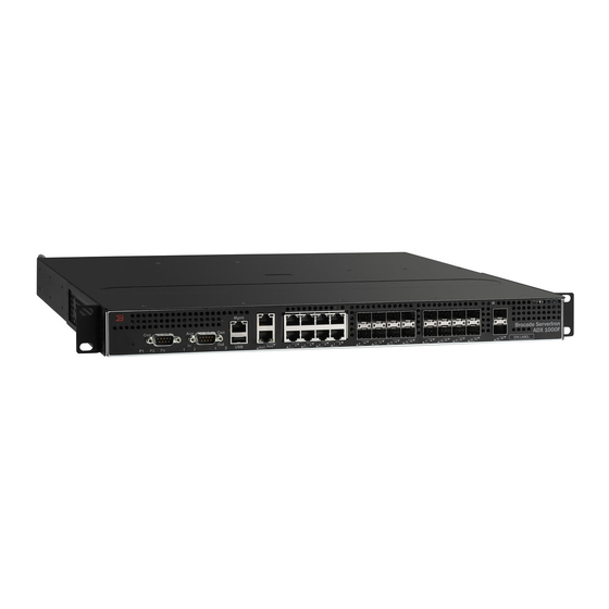
Chapter Product Overview ServerIron ADX fixed configuration devices This section describes the ServerIron ADX 1000 and ServerIron ADX 1000F fixed configuration devices.. ServerIron ADX 1000 Figure 1 shows the ServerIron ADX 1000 fixed configuration device for each model. FIGURE 1... -
Page 12: Serveriron Adx 1000F
ServerIron ADX chassis devices ServerIron ADX 1000F Figure 1 shows the ServerIron ADX 1000F fixed configuration device for each model. FIGURE 2 ServerIron ADX 1000F Chassis Mgmt Aux1 Aux2 9 10 11 12 13 14 15 16 17 18 ServerIron ADX 1000F is available in these four configurations: •... - Page 13 ServerIron ADX chassis devices SI-12GC SI-ASM Application Switch Module Lnk / Act Lnk / Act Console ASM1 1 2 3 4 5 6 7 8 Mgmt SI-MM SI-SFM Console Aux1 Aux2 Console SI-ASM Application Switch Module SI-12GC Lnk / Act Lnk / Act Console ASM2...
-
Page 14: Serveriron Adx 10000 (Adx 10K) Chassis
ServerIron ADX chassis devices ServerIron ADX 10000 (ADX 10K) chassis Figure 4 shows the ServerIron ADX 10000 chassis. FIGURE 4 ServerIron ADX 10000 Chassis SYSTEM AC OK DC OK Brocade ServerIron ADX 10000 SYSTEM AC OK DC OK SYSTEM AC OK DC OK SYSTEM AC OK DC OK ServerIron ADX 10000 chassis basics:... -
Page 15: Serveriron Adx Chassis Device Modules
ServerIron ADX Chassis device modules • Four AC or DC power supplies (two required, one or two redundant) Slot ordering for ServerIron ADX 10000 is important. Refer to “Installing modules in ServerIron ADX chassis devices” on page 21. ServerIron ADX Chassis device modules The ServerIron ADX chassis devices accommodate the modules described in this section: •... -
Page 16: Application Switch Module (Asm)
ServerIron ADX Chassis device modules 12 x 1G Copper Figure 6 shows the front panel for the 12 x 1G copper module. FIGURE 6 12 x 1G Copper Modular Ethernet Interface Module SI-12GC Lnk / Act Lnk / Act 12 x 1G SFP Fiber Figure 7 shows the front panel for the 12 x 1G SFP fiber module. -
Page 17: Management Module (Mm)
ServerIron ADX Chassis device modules ServerIron ADX 4000 systems accommodate up to two ASMs. ServerIron ADX 8000 and ServerIron ADX 10000 systems accommodate up to four ASMs. Each ASM has the following features: • Eight Application Cores (the number of application cores avaialable depends on the license that is bound to the module) •... -
Page 18: Switch Fabric Module (Sfm)
ServerIron ADX Chassis device modules Switch Fabric Module (SFM) Figure 10 shows the Switch Fabric Module (SFM) front panel. One SFM is required for ServerIron ADX 4000. Two are required for ServerIron ADX 8000 and ServerIron ADX 10000. FIGURE 10 Switch Fabric Module Front Panel SI-SFM The front panel includes a LED that, when lit, indicates that the module is receiving power. -
Page 19: Power Supplies
ServerIron ADX 1000 and ServerIron ADX 1000F power supplies ServerIron ADX 1000 and SServerIron ADX 1000F raccommodate up to two power supplies (AC or DC) with one required and one redundant. You install the power supplies (AC or DC) at the back of the chassis. Each power supply has one LED on its faceplate to provide status. -
Page 20: Cooling Systems
ServerIron ADX 1000 and ServerIron ADX 1000F cooling system The ServerIron ADX 1000 and ServerIron ADX 1000F are equipped with a fan tray containing variable-speed fans and fan controllers. Figure 12 shows how the fan assembly slides into the back of the chassis. -
Page 21: Serveriron Adx 4000 And Serveriron Adx 8000 Cooling Systems
Cooling systems ServerIron ADX 4000 and ServerIron ADX 8000 cooling systems The ServerIron ADX 4000 and ServerIron ADX 8000 cooling systems are equipped with a fan tray containing variable-speed fans and six fan controllers to support redundancy. ServerIron ADX 4000 contains three fans and controllers, and ServerIron ADX 8000 contains six fans and controllers. -
Page 22: Serveriron Adx 10000 Cooling Systems
Rack mounting ServerIron ADX 10000 cooling systems The ServerIron ADX 10000 cooling system provides for front-to-back cooling. It is equipped with a fan tray containing six variable-speed fans to support redundancy. The fan tray has a fan filter that can be changed while the ServerIron ADX 10000 is in operation. Refer to Figure FIGURE 14 Fan Tray Front View for the ServerIron ADX 10000... -
Page 23: Installing Serveriron Adx
Chapter Installing ServerIron ADX Installation precautions This chapter contains information on how to install a ServerIron ADX. Before proceeding, please read the cautions and warnings below that apply to the entire ServerIron ADX family. DANGER The procedures in this manual are for qualified service personnel only. DANGER If the installation requires a different power cord than the one supplied with the device, make sure you use a power cord displaying the mark of the safety agency that defines the regulations... -
Page 24: General Precautions
Installation precautions General precautions CAUTION Risk of explosion if battery is replaced by an incorrect type. Replace the battery only with the same or equivalent type recommended by the manufacturer. Lithium battery is a long life battery and it is very possible that you will never need to replace it. However, should you need to replace it, do not dispose of the battery along with household waste. -
Page 25: Lifting Precautions
Installation precautions Lifting precautions DANGER Make sure the rack or cabinet housing the device is adequately secured to prevent it from becoming unstable or falling over. DANGER Mount the devices you install in a rack or cabinet as low as possible. Place the heaviest device at the bottom and progressively place lighter devices above. - Page 26 Installation precautions CAUTION Remove the power cord from a power supply before you install it in or remove it from the device. Otherwise, the power supply or the device could be damaged as a result. (The device can be running while a power supply is being installed or removed, but the power supply itself should not be connected to a power source.) CAUTION The power supply is designed exclusively for use with the ServerIron devices.
-
Page 27: Installing Serveriron Adx
For a DC system, use a grounding wire of at least 6 American Wire Gauge (AWG). The 6 AWG wire should be attached to an agency-approved crimp connector, crimped with the proper tool This Caution Applies to the ServerIron ADX 1000 CAUTION For the DC input circuit to the system, it must be connected to a 20 amp circuit breaker, minimum -48Vdc, double pole, on the input to the terminal block. -
Page 28: Preparing The Installation Site
Installing ServerIron ADX Preparing the installation site This section describes how to prepare for installation. Cabling infrastructure Ensure that the proper cabling is installed at the site. For information on cabling, refer to “Installing power supplies” on page 26 and “Attaching a management station”... - Page 29 ServerIron ADX 4000, ServerIron ADX 8000 and ServerIron ADX 10000. Do not secure the screws completely; leave approximately 1/4 inch of clearance between the back of the screw head and the rack. FIGURE 15 Positioning the Screws in a Rack - ServerIron ADX 1000 Brocade ServerIron ADX Installation Guide 53-1002405-01...
- Page 30 Installing ServerIron ADX FIGURE 16 Positioning the Screws in a Rack - ServerIron ADX 4000, ServerIron ADX 8000 and ServerIron ADX 10000 3. Starting with the chassis that you want to mount in the lowest position in the rack, mount the chassis in the rack.
-
Page 31: Installing Modules In Serveriron Adx Chassis Devices
Installing ServerIron ADX Although the slot blanks are different in size, the procedure for removing them from the chassis is the same. Therefore, this section provides one procedure that applies to all slot blanks. You will need a flat-head screwdriver to perform this task. To remove a slot blank, follow these steps. - Page 32 Installing ServerIron ADX The ServerIron ADX 4000 chassis ships with the following components installed (see shaded slots Figure 17): • One SFM • Fan tray • One power supply FIGURE 17 Slot Ordering for the ServerIron ADX 4000 Chassis ServerIron 4000 Front Panel View ASM 1 INTERFACE MODULE 1 MM 1...
- Page 33 Installing ServerIron ADX Information about the slot locations for the ServerIron ADX 8000 chassis is described in Appendix B, “ServerIron ADX 8000”. CAUTION If you do not install a module in a slot, you must leave the blank slot module installed in the slot. If you run the chassis with an uncovered slot, the system may overheat.
-
Page 34: Installing An Ssl Expansion Module Onto A Management
Installing ServerIron ADX FIGURE 19 Installing a Module in a ServerIron ADX chassis device NOTE When inserting the module into the chassis, make sure that the faceplate does not overlap with the faceplate of an adjacent ASM Module. 4. Push the ejectors in until they are flush with the module front panel. This action will fully seat the module in the backplane. - Page 35 Installing ServerIron ADX SSL Upgrade Kit contents Table 1 lists the items that are included in your ServerIron ADX SSL Upgrade Kit. TABLE 1 ServerIron ADX SSL Upgrade Kit contents Description Quantity SSL Expansion Module 4-40 nuts with Phillips drive 4-40 x 3/8 phillips drive pan head screws FIGURE 20 ServerIron ADX SSL Upgrade Kit contents...
-
Page 36: Installing Power Supplies
Installing ServerIron ADX FIGURE 21 Securing the nuts to the posts 1 Posts 2 14-40 nuts with Phillips drive 3 SSL Expansion module 4 Management module 6. Locate the 6 mounting holes and using a Phillips screwdriver fasten the SSL Expansion module to the ServerIron ADX Management Module with the six screws. - Page 37 ServerIron ADX 1000 and ServerIron ADX 1000F power supplies The ServerIron ADX 1000 and ServerIron ADX 100F can accommodate up to two power supplies (AC or DC). It is shipped with one power supply. An additional power supply can be purchased for 1+1 power supply redundancy.
- Page 38 Installing ServerIron ADX ServerIron ADX chassis device power supplies The ServerIron ADX 4000 accommodates up to two power supplies (AC or DC). It is shipped with one power supply, which is required to run the system. The ServerIron ADX 8000 chassis accommodates up to four power supplies (AC or DC). It is shipped with two power supplies, both of which are required to run the system.
-
Page 39: Connecting Ac Power
2. Lift the cord-retainer and connect a Brocade-supplied AC power cord to the power supply. 3. Snap the cord-retainer over the power plug to hold it in place. FIGURE 25 AC Power Connections on the ServerIron ADX 1000 Chassis 1 Power Supply Status LED Brocade ServerIron ADX Installation Guide... - Page 40 Installing ServerIron ADX FIGURE 26 AC Power Connections on the ServerIron ADX 4000 Chassis 100-240 VAC 48 VDC SEE REAR LABEL FIGURE 27 AC Power Connections on the ServerIron ADX 8000 Chassis AC OK AC OK DC OK DC OK AC OK DC OK AC OK...
-
Page 41: Connecting Dc Power To A Chassis
Installing ServerIron ADX DANGER If the installation requires a different power cord than the one supplied with the device, make sure you use a power cord displaying the mark of the safety agency that defines the regulations for power cords in your country. The mark is your assurance that the power cord can be used safely with the device. - Page 42 1 Wire Tightening Screws 2 Assembly Screws 3. Push the DC wiring assembly into the power supply and attach it using the assembly screws. Slide the DC power supply into the ServerIron ADX 1000 chassis and tighten it using the chassis attachment screws.
- Page 43 Installing ServerIron ADX FIGURE 30 Inserting the ServerIron ADX 1000 DC Wiring Assembly 1 Chassis Attachment Screws 2 Assembly Screws 5. Connect the wire to your DC power source, making sure to connect the -48V cable to the negative terminal on the power supply and the 0V cable to the positive terminal as marked on the power supply.
-
Page 44: Connecting Dc Power To Serveriron Adx Chassis Devices
Installing ServerIron ADX CAUTION When making the primary ground connection, a star washer must be used for anti-rotation. When connecting the device to the rack frame, use thread-forming screws and paint-piercing washers. CAUTION AC and DC power supplies can be grounded to a common bonding network or to an isolated bonding network. - Page 45 Installing ServerIron ADX CAUTION To insure adequate bonding when attaching the ground lug, a minimum of 20 PSI of torque is required to be applied to the mounting hardware used to attach the ground lug. CAUTION When making the primary ground connection, a star washer must be used for anti-rotation. When connecting the device to the rack frame, use thread-forming screws and paint-piercing washers.
-
Page 46: Attaching A Management Station
Attaching a management station Attaching a management station You can manage the ServerIron ADX system in the following ways: • You can connect a PC or terminal to the Management Module (MM) serial (console) port for a direct connection. From this interface, you can configure the 10BaseT/100BaseTX/1000BaseTX Ethernet management port with an IP address for Telnet or SSH access to the system. -
Page 47: Attaching The Management Module Ethernet Port To A Network37
Powering On the power source • Flow control: None Attaching the management module Ethernet port to a network The Management Module (MM) 10BaseT/100BaseTX/1000BaseTX Ethernet (management) port (RJ-45 UTP connector) allows you to connect the management port to a network. To attach the MM Ethernet port to a network, you need a Category 5 UTP straight-through cable (not supplied by Brocade). -
Page 48: Uninstalling Serveriron Adx Modules
Uninstalling ServerIron ADX modules 4. Verify that ServerIron ADX has initialized successfully. For information, refer to “Verifying proper operation” in the next section. DANGER The intra-building port(s) of the equipment or subassembly is suitable for connection to intra-building or unexposed wiring or cabling only. The intra-building port(s) of the equipment or subassembly MUST NOT be metallically connected to interfaces that connect to the OSP or its wiring. -
Page 49: Uninstalling An Application Switch Module
Uninstalling ServerIron ADX modules • Selecting the slot-lc3 parameter disables the Interface module in slot 3 of the ServerIron ADX 8000 & 10000 chassis. • Selecting the slot-lc4 parameter disables the Interface module in slot 4 of the ServerIron ADX 4000, 8000 &... -
Page 50: Uninstalling A Management Module
Uninstalling ServerIron ADX modules Uninstalling a Management module When removing an Active Management module from a ServerIron ADX 4000, ServerIron ADX 8000 or ServerIron ADX 10000 you must shutdown and power-off the system first. It can then be physically removed from the chassis. When removing an Standby Management module from an operating ServerIron ADX 8000 or ServerIron ADX 10000 you should perform the following actions in the order shown: 1. -
Page 51: Uninstalling A Power Supply
Installing ServerIron ADX modules in a running system • When the temperature of a Switch Fabric module is exceeded, it is shutdown which disrupts operation of the entire ServerIron ADX. You can however, briefly remove a Fan Tray from an operating ServerIron ADX 4000, ServerIron ADX 8000 or ServerIron ADX 10000 for a few seconds and replace it with a new one before the shutdown temperature thresholds are reached. -
Page 52: Installing An Interface Module In A Running System
Installing ServerIron ADX modules in a running system Installing an Interface module in a running system You can install Interface modules into a running system without any service disruption. When the Interface module is inserted in its designated slot in the ServerIron ADX chassis, it is automatically detected and brought online. -
Page 53: Verifying Proper Operation
LEDs for the ServerIron ADX 1000/1000F, including possible states and meanings. If a problem persists after taking action described in this table, contact Brocade technical support. TABLE 2 LED States After System Power On - ServerIron ADX 1000 and ServerIron ADX 1000F State Meaning 1G Interface Ports A link is established with the remote port (no traffic). - Page 54 Verifying proper operation TABLE 2 LED States After System Power On - ServerIron ADX 1000 and ServerIron ADX 1000F (Continued) State Meaning Out 1 Blinking Packets are currently being sent from BP1. No packets are currently being sent from BP1.
-
Page 55: Matching Leds To Locations On The Serveriron Adx 1000 And Serveriron Adx 1000F
3 LEDs for 1G Copper Interface Ports 5 LEDs for 10G Interface Ports 2 LEDs for Application Cores 4 LEDs for 1G Fibe rInterface Ports Figure 35 shows the AC power supply LED on the ServerIron ADX 1000 (and ServerIron ADX 1000F), and Figure 36 shows the DC LED. -
Page 56: Observing The Leds - Serveriron Adx Chassis Devices
Verifying proper operation 1 Power Supply Status LED Observing the LEDs - ServerIron ADX chassis devices After a ServerIron ADX chassis powers on, you can observe its LEDs to verify that it initialized successfully. Table 3 lists the LEDs for the ServerIron ADX 4000, ServerIron ADX 8000 and ServerIron ADX 10000, including desired states, meanings, abnormal states, and possible actions to state to respond to abnormal states. - Page 57 Verifying proper operation TABLE 3 LED States After System Power On - ServerIron ADX 4000, ServerIron ADX 8000 and ServerIron ADX 10000 (Continued) Desired State Meaning Abnormal State Meaning/Action BP In Blinking Activity on Barrel No packets are currently being received Processor (BP).
- Page 58 Verifying proper operation TABLE 3 LED States After System Power On - ServerIron ADX 4000, ServerIron ADX 8000 and ServerIron ADX 10000 (Continued) Desired State Meaning Abnormal State Meaning/Action Mgmt On or blinking (yellow) The port is transmitting Off for an The port is not transmitting or receiving (10/100/1000 and receiving packets.
- Page 59 Verifying proper operation TABLE 3 LED States After System Power On - ServerIron ADX 4000, ServerIron ADX 8000 and ServerIron ADX 10000 (Continued) Desired State Meaning Abnormal State Meaning/Action 12 x 1G Copper Ethernet Interface Module The module is receiving The module is not receiving power.
- Page 60 Verifying proper operation TABLE 3 LED States After System Power On - ServerIron ADX 4000, ServerIron ADX 8000 and ServerIron ADX 10000 (Continued) Desired State Meaning Abnormal State Meaning/Action Power Supplies AC AC OK Green (steady) The power supply is The power supply is not receiving power receiving AC power from from an AC power source You can do...
-
Page 61: Matching Leds To Locations On Serveriron Adx Chassis Device Modules
Verifying proper operation Matching LEDs to locations on ServerIron ADX chassis device modules Figure 37 shows how to match the LEDs to ports on the 4 x 10G XFP Fiber Ethernet Interface Module. FIGURE 37 Interpreting LEDs on the 4 x 10G XFP Fiber Ethernet Interface Module 1 LEDs for Port 1 3 LEDs for Port 3 2 LEDs for Port 2... -
Page 62: Replacing A Fan Tray
Replacing a Fan Tray Figure 39 shows how to match the LEDs to ports on the 12 x 1G SFP Fiber Ethernet Interface Module. FIGURE 39 Interpreting LEDs on the 12 x 1G SFP Fiber Ethernet Interface Module Lnk / Act Lnk / Act Lnk / Act 1 LED for Upper Port... -
Page 63: Replacing The Serveriron Adx 1000 Or Serveriron Adx 1000F Fan Tray
Replacing a Fan Tray Replacing the ServerIron ADX 1000 or ServerIron ADX 1000F Fan Tray To replace the ServerIron ADX 1000 fan tray, follow these steps. 1. Power down and unplug the chassis. 2. Unscrew the two screws that secure the fan tray to the chassis (Figure 40). -
Page 64: Replacing The Serveriron Adx 10000 Fan Tray
Replacing a Fan Tray Replacing the ServerIron ADX 10000 Fan Tray To replace the ServerIron ADX 10000 fan tray, follow these steps. 1. Power down and unplug the chassis. 2. Use a #2 phillips screwdriver to loosen the captive screws. These are the silver screws. 3. - Page 65 Replacing a Fan Tray FIGURE 42 Replacing a Fan from a ServerIron ADX 10000 Handle Fan Tray Handle Brocade ServerIron ADX Installation Guide 53-1002405-01...
-
Page 66: Replacing The Air Filter In The Serveriron Adx 10000
Replacing a Fan Tray Replacing the air filter in the ServerIron ADX 10000 The fan filter in the ServerIron ADX 10000 can be replaced with the fan assembly installed in the chassis and in operation as described in the following steps. 1. -
Page 67: Hardware Specifications
This section contains the power specifications for the ServerIron ADX chassis. Table 4 provides the maximum power calculations. TABLE 4 Maximum Power Calculations ServerIron ADX Chassis Watts ServerIron ADX 1000 ServerIron ADX 1000F ServerIron ADX 4000 ServerIron ADX 8000 1920 ServerIron ADX 10000 1920... -
Page 68: Physical Dimensions
137W SSL Expansion module Table 6 lists the operating voltage and current ratings for ServerIron ADX 1000/1000F. TABLE 6 ServerIron ADX 1000 and ServerIron ADX 1000F operating voltage and current ratings Power Supply Input Voltage Range Input Current Inrush Current Maximum Output º... -
Page 69: Storage Environment
Port specifications TABLE 9 Operating Environment Operating Temperature Relative Humidity Operating Altitude 32× – 104× F (0× – 40× C) 5 to 90%, at 104× F (40× C), non-condensing 0 – 6600 ft (0 – 2012 meters) Storage environment Table 10 provides the storage environment specifications for the ServerIron ADX chassis. -
Page 70: Console Port Pin Assignments
Port specifications CAUTION The intra-building port(s) of the equipment or subassembly is suitable for connection to intra-building or unexposed wiring or cabling only. The intra-building port(s) of the equipment or subassembly MUST NOT be metallically connected to interfaces that connect to the OSP or its wiring. -
Page 71: Management Port Pin Assignments
Port specifications DB-9 to DB-9 DB-9 to DB-25 Terminal or PC Terminal or PC Female Switch Female Switch Reserved Reserved Reserved Reserved Reserved Reserved Reserved Reserved Management Port Pin assignments The management port is an RJ-45 UTP connector. Table 11 describes the connector pin assignments. - Page 72 Port specifications Brocade ServerIron ADX Installation Guide 53-1002405-01...
-
Page 73: Serveriron Adx 8000
Appendix ServerIron ADX 8000 The ServerIron ADX 8000 was replaced with the ServerIron 10000 and is no longer available from Brocade. It is still supported by Brocade however and it will run all new ServerIron ADX software releases. This appendix provides all of the ADX 8000 specific features while all installation and operation details are described in the body of this guide where the ServerIron ADX chassis devices are described. -
Page 74: Serveriron Adx 8000 Slot Assignments
ServerIron ADX 8000 Two power supplies are required, and two are optional for redundancy. By default, the system ships with two power supplies. • One hot-pluggable fan tray with six fans • Side-to-side air cooling - left-to-right • Card slots to accommodate modules A fully-loaded ServerIron ADX 8000 can accommodate the following components: •... - Page 75 ServerIron ADX 8000 Brocade ServerIron ADX Installation Guide 53-1002405-01...
- Page 76 ServerIron ADX 8000 Brocade ServerIron ADX Installation Guide 53-1002405-01...
-
Page 77: Regulatory Statements
Appendix Regulatory Statements U.S.A. This equipment has been tested and found to comply with the limits for a Class A digital device pursuant to Part 15 of the FCC Rules. These limits are designed to provide reasonable protection against harmful interference when the equipment is operated in a commercial environment. This equipment generates, uses, and can radiate radio frequency energy and, if not installed and used in accordance with the instruction manual, may cause harmful interference to radio communications. -
Page 78: Japan
Japan Japan English Translation of above statement This is Class A product based on the standard of the Voluntary Control Council For Interference by Information Technology Equipment (VCCI). If this equipment is used in a domestic environment, radio disturbance may arise. When such trouble occurs, the user may be required to take corrective actions. -
Page 79: Bmsi Statement (Taiwan)
BMSI STATEMENT (TAIWAN) English translation of above statement This apparatus has radio wave acceptability registration as a Class A device, so sellers or users should be aware of this. If it is sold or purchased incorrectly, it should be exchanged with a home apparatus (Class B). - Page 80 BMSI STATEMENT (TAIWAN) Brocade ServerIron ADX Installation Guide 53-1002405-01...
-
Page 81: Cautions And Danger
Appendix Cautions and Danger The cautions and warnings that appear in this manual are listed below in English, German, French, and Spanish. Cautions A caution calls your attention to a possible hazard that can damage equipment. “Vorsicht” weist auf eine mögliche Beschädigung des Geräts hin. Sie finden die folgenden Vorsichtshinweise in diesem Handbuch. - Page 82 Cautions CAUTION Do not add or remove a flash card while a file operation involving the flash card's slot is in progress. Doing so can result in corruption of the flash card. If this occurs, you may need to reformat the flash card to make it usable again.
- Page 83 Cautions CAUTION All devices with AC power sources (ServerIron 4000, 8000 only) are intended for installation in restricted access areas only. A restricted access area is a location where access can be gained only by service personnel through the use of a special tool, lock and key, or other means of security. VORSICHT Alle Geräte mit Wechselstromquellen (ServerIron 4000, 8000 nur) sind nur zur Installation in Sperrbereichen bestimmt.
- Page 84 Cautions CAUTION Never leave tools inside the chassis. VORSICHT Lassen Sie keine Werkzeuge im Chassis zurück. MISE EN GARDE Ne laissez jamais d'outils à l'intérieur du châssis. PRECAUCIÓN No deje nunca herramientas en el interior del chasis. CAUTION Once you start the formatting process, you cannot stop it. Even if you enter CTRL-C to stop the CLI output and a new prompt appears, the formatting continues.
- Page 85 Cautions CAUTION To avoid overheating of the chassis, remove only one fan assembly at a time. VORSICHT Es darf nur ein Ventilatorblech zur Zeit entfernt werden, um ein Überhitzen des chassis Gehäuses zu vermeiden. Es dürfen nicht beide Ventilatorbleche auf einmal entfernt werden. MISE EN GARDE Pour éviter la surchauffe du châssis, n'enlever qu'un seul boîtier de ventilateur à...
- Page 86 Cautions This Caution Applies to the ServerIron ADX 1000 CAUTION For the DC input circuit to the system, it must be connected to a 20 amp circuit breaker, minimum -48Vdc, double pole, on the input to the terminal block. The input wiring for connection to the product should be copper wire, 12 AWG, marked VW-1, and rated minimum 90 degrees celcius.
- Page 87 Cautions CAUTION Product contains ESD sensitive devices, use proper ESD mitigation procedures (such as ESD grounding wrist straps) before handling. VORSICHT Das Produkt enthält ESD-gefährdete Bauteile. Treffen Sie vor der Arbeit geeignete ESD-Schutzvorkehrungen, z. B. ESD-Erdungsarmbänder. MISE EN GARDE Le produit contient des composants sensibles aux décharges électrostatiques. Appliquez les procédures d'atténuation des décharges électrostatiques (port de bracelet antistatique par exemple) avant toute manipulation.
- Page 88 Cautions CAUTION Slot ordering and type for ServerIron ADX 4000, ServerIron ADX 8000 and ServerIron ADX 10000 is important. Each module is keyed according to type. Do not attempt to force a module into a slot that is not intended for that module type.
- Page 89 Cautions PRECAUCIÓN Es importante el orden y el tipo de las ranuras de Serverlon ADX 4000, ServerIron ADX 8000 y ServerIron ADX 10000. Cada módulo está marcado según el tipo al que pertenece. No intente introducir a la fuerza un módulo en una ranura que no haya sido diseñada para ese tipo de módulo.
- Page 90 Cautions CAUTION For the NEBS compliant installation of a ServerIron ADX device with AC and DC system use a ground wire of at least 6 American Wire Gauge (AWG). The ground wire should have an agency-approved crimped connector (provided with the chassis) attached to one end, with the other end attached to building ground. The connector must be crimped with the proper tool, allowing it to be connected to both ground screws on the enclosure.
-
Page 91: Danger
Danger CAUTION The power supply is designed exclusively for use with the ServerIron devices. The power supply produces extensive power. Installing the power supply in a device other than a ServerIron will cause damage to your equipment. VORSICHT Das Netzteil ist nur für die Verwendung mit ServerIron-Geräten ausgelegt. Das Netzteil liefert hohe Strompegel. Der Einbau des Netzteils in anderen als ServerIron-Geräten führt zu Schaden an den Geräten. - Page 92 Danger DANGER If the installation requires a different power cord than the one supplied with the device, make sure you use a power cord displaying the mark of the safety agency that defines the regulations for power cords in your country. The mark is your assurance that the power cord can be used safely with the device.
- Page 93 Danger DANGER For safety reasons, the ESD wrist strap should contain a series 1 meg ohm resistor. GEFAHR Aus Sicherheitsgründen sollte ein EGB-Armband zum Schutz von elektronischen gefährdeten Bauelementen mit einem 1 Megaohm-Reihenwiderstand ausgestattet sein. DANGER Pour des raisons de sécurité, la dragonne ESD doit contenir une résistance de série 1 méga ohm. PELIGRO Por razones de seguridad, la correa de muñeca ESD deberá...
- Page 94 Danger DANGER A fully-populated ServerIron ADX chassis is heavy. TWO OR MORE PEOPLE ARE REQUIRED WHEN LIFTING, HANDLING, OR MOUNTING THESE DEVICES. GEFAHR Ein voll bestücktes ServerIron ADX Gehäuse ist schwer. ZUM ANHEBEN, HANDHABEN ODER MONTIEREN DIESER GERÄTE SIND MINDESTENS ZWEI PERSONEN ERFORDERLICH. DANGER Un châssis ServerIron ADX entièrement équipé...
- Page 95 Danger DANGER DC return shall be isolated from the chassis ground (DC-I) when connections to the power supply are made. GEFAHR Beim Herstellen der Verbindungen mit dem Netzteil muss der Gleichstrom-Rückleiter von der Gehäusemasse (DC-I) isoliert werden. DANGER Le retour CC doit être isolé du système de mise à la terre du châssis lors de la connexion du bloc d'alimentation. PELIGRO El retorno de CC debería aislarse de la toma de tierra del chasis (CC-I) cuando se realicen conexiones al suministro de energía.
Need help?
Do you have a question about the ServerIron ADX 1000 and is the answer not in the manual?
Questions and answers