Table of Contents
Advertisement
Quick Links
Repair and Parts
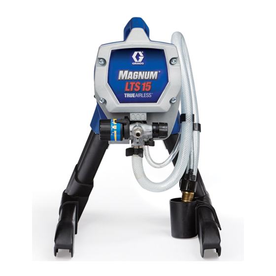
LTS 15, LTS 17, ProLTS 17 and
ProLTS 19 Airless Sprayers
- For portable spray applications of architectural paints and coatings -
Models 257060, 257065, 257070, 257080,
24N906, 24N808
3000 psi (21 MPa, 207 bar) Maximum Working Pressure
See page 2 for model and series information including
dispense rate, recommended hose length, guns, and
maximum working pressure.
IMPORTANT SAFETY INSTRUCTIONS.
Read all warnings and instructions in this
manual. Save these instructions.
Related Manual
313034
ti11305a
M
LTS 17
AGNUM
Model: 257065
Series A, B
ti9369a
M
ProLTS 17
AGNUM
M
AGNUM
Model: 24N906
Model: 257070
Series A
LTS 15 & LTS 17 Models ONLY:
mineral spirit-type materials only. Do not use materials
having flash points lower than 70° F (21° C). This
includes, but is not limited to, acetone, xylene, toluene, or
naptha. For more information about your material, request
MSDS from distributor or retailer.
ti9369b
ProLTS 17
M
AGNUM
Model: 257080
Series A
Series A
Visit our website;
http://M
LTS.Graco.com
AGNUM
313036N
Use water-based or
M
LTS 15
AGNUM
Model: 257060
Series A, B, C
ti11304a
ti9368a
M
ProLTS 19
AGNUM
Model: 24N808
Series A
EN
ti9368b
ProLTS 19
Advertisement
Table of Contents
Troubleshooting


Need help?
Do you have a question about the LTS 15 and is the answer not in the manual?
Questions and answers