Advertisement
Quick Links
Advertisement

Related Manuals for Roban B 205/UH-1D

Summary of Contents for Roban B 205/UH-1D
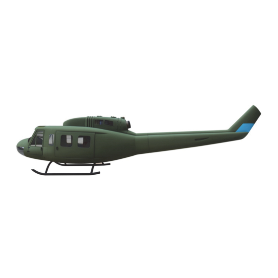
- Page 1 B 205/UH‐1D 800 size, including SM2.0 mechanics Manual CCPM SCALE RC HELICOPTER ...
- Page 2 Super Scale 800 Manual – B 205 / UH1D Release 2.0 ‐ January 2016 Roban Limited Zhengyacun Industrial Zone, Venture Cross Rd. Jiaolian, Wanjiang City District of Dongguan, 523046 Dongguan County (GD) ‐ PRC Copyright@2016 - Roban Limited – All rights reserved...
-
Page 3: Specifications
Battery:* 44.4V 5000mAh 35C+ Flight time: 5 minutes Takeoff weight: 8500g Flight Stabilization:* 3 axis flybarless gyro Radio Control:* min. 6 channel with pitch and throttle curves *) Optionally available equipment The Compactor is a high performance radio controlled scale helicopter. Our goal was to create a simple, high performance helicopter, with a minimum of mechanical components and simple maintenance. Please read this user manual carefully, it contains instructions for the correct assembly of the model. Please refer to the web site www.robanmodel.com for updates and other important information. Thank you for your purchase, and have a great time with your Compactor! Roban Limited Copyright@2016 - Roban Limited – All rights reserved... -
Page 4: Important Notes
*A radio controlled helicopter must only be used in open spaces without obstacles, and far enough from people to minimize the possibility of accidents or of injury to property or persons. *A radio controlled helicopter can behave in an unexpected manner, causing loss of control of the model, and make it a very dangerous flying object. *Lack of care with assembly or maintenance can result in an unreliable and dangerous model. *Neither Roban Limited nor its agents have any control over the assembly, maintenance and use of this product. Therefore, no responsibility can be traced back to the manufacturer. You hereby agree to release Roban Limited from any responsibility or liability arising from the use of this product. SAFETY GUIDELINES *Fly only in areas dedicated to the use of model helicopters. *Follow all control procedures for the radio frequency system. *It is necessary that you know your radio system well. Check all functions of the transmitter before every flight. *The blades of the model rotate at a very high speed; be aware of the danger they pose and the damage they may cause. *Never fly in the vicinity of other people. NOTES FOR ASSEMBLY Please refer to this manual for assembly instructions for this model. Follow the order of assembly indicated. The instructions are divided into chapters, which are structured in a way that each step is based on the work done in the previous step. Changing the order of assembly may result in additional or unnecessary steps. Use thread lockers and retaining compounds as indicated. In general, each bolt or screw that engages with a metal part requires thread lock. Factory pre‐assembled components have been assembled with all the required thread lock and lubricants, and have passed quality control. It is not necessary to disassemble and re‐assemble them. We do not recommend the use of thin cyanoacrylate glue for surface mount of painted parts. The fumes of the curing glue leave white stains on the clear coat, which are hard to remove. Copyright@2016 - Roban Limited – All rights reserved... - Page 5 33 – Screw M3x10 x6 34 – Ball link x4 35 – Nut M2 x4 36 – Nut M3 x4 Copyright@2016 - Roban Limited – All rights reserved...
- Page 6 67 – Side seat x2 68 – Center seat 69 – Front seat x2 70 – Scale part x2 71 – Scale part x2 72 – Scale part x2 Copyright@2016 - Roban Limited – All rights reserved...
- Page 7 73 – Scale part x2 74 – Center seat post x2 75 – Cockpit light 76 - Decal set connector wire Copyright@2016 - Roban Limited – All rights reserved...
-
Page 8: Additional Components Required
ADDITIONAL COMPONENTS REQUIRED TOOLS, LUBRICANTS, ADHESIVES *Electric Motor: *Generic pliers 12S – 450KV (412) /530KV(212) 750MX, or similar *Hexagonal driver, size 1.5, 2, 2.5, 3, 4mm pinion shaft diameter 6mm *4mm T‐Wrench *Speed controller: *5.5mm Socket wrench (for M3 nuts) minimum 120A to be safe *8mm Hex fork wrench (for M5 nuts) *Batteries: 10‐12S 4000‐5000mAh *Medium threadlocker (eg. Loctite 243) *1 flybarless 3 axis control unit, suitable for scale flying *Strong retaining compound (eg. Loctite 648) *Radio power system *Spray lubricant (eg. Try‐Flow Oil) *3 cyclic servos *Synthetic grease (eg. Tri‐Flow Synthetic Grease) *1 tail rotor servo *Cyanoacrylate adhesive *6 channel radio control system on 2.4 GHz *Pitch Gauge (for set‐up) *Soldering equipment (for motor wiring) Inside the main box there are: Inside the main box: Bag 1: Manual ... - Page 9 Assembly Scale Fuselage Prior to installing the mechanics into the fuselage, please prepare the fuselage according to the following steps. Installation into the fuselage most of the helicopter mechanic become inaccessible. The landing gear has to be installed first. As you will have to turn the mechanics over, please make sure that you are not scratching the paint by using a old blanket or a rig while working on it. ...
- Page 10 Copyright@2016 - Roban Limited – All rights reserved...
- Page 11 Copyright@2016 - Roban Limited – All rights reserved...
- Page 12 Copyright@2016 - Roban Limited – All rights reserved...
- Page 13 Copyright@2016 - Roban Limited – All rights reserved...
- Page 14 Copyright@2016 - Roban Limited – All rights reserved...
- Page 15 Copyright@2016 - Roban Limited – All rights reserved...
- Page 16 Copyright@2016 - Roban Limited – All rights reserved...
- Page 17 Copyright@2016 - Roban Limited – All rights reserved...
- Page 18 Assembly Mechanics The mechanics are almost entirely preassembled and split up into four sections: rotorhead, main frame, tail frame and tail tube. Prior to the installation into the scale fuselage, the mechanics have to be entirely assembled, electronic components installed, adjusted and tested. After installation into the fuselage most of the helicopter mechanic become inaccessible. Step 1 – Rotorhead Slide the rotorhead onto the main shaft. Use screw (70‐ Make sure that you time the rotor head properly. The L‐Lever 00006) and nylon nut (70‐00007) to secure the rotorhead has to be adjusted so that the control rods are parallel to the ...
- Page 19 Depending on your servos, you may have to use washers to linkage rods length’s according to the schematics below. The adjust the servo to the proper installation height. It is strongly distances are uniball center to uniball center: recommended to use metal servo horns and only metal 1=81mm 2=112mm 3=81mm geared servos. The multi blade rotor head can feedback forces that may lead to failure of plastic components. Copyright@2016 - Roban Limited – All rights reserved...
- Page 20 Step 5 – Adjust swashplate linkages The linkages from the L‐Levers to the swash plate have to be set at correct length. Distances are uniball center to uniball center: 1=35mm Step 6 – Motor and Belt installation In order to install the motor, you must first disassemble one Mount the motor as shown using washers and screws onto of ...
- Page 21 Fig. (1) Secondary Motor Support Certain motors with 25mm mounts and long output shafts can be outfitted with a secondary motor shaft bearing. ...
- Page 22 Step 7 – Electrical Wiring and Setup The mechanics have to be fully electrically setup and adjusted prior to installation into the fuselage. As the use of a 12S ATTENTION ! (44.4V) setup is necessary, we strongly recommend to run the control equipment on a separate 2S Lipo battery and BEC for When using the a pitch gauge to adjust correct CP travels, security reasons. make sure that the gauge lines up with the flat surface of ...
- Page 23 Step 8 – Installation of mechanics Remove the short tail boom as shown. ...
- Page 24 Copyright@2016 - Roban Limited – All rights reserved...
- Page 25 Copyright@2016 - Roban Limited – All rights reserved...
- Page 26 Copyright@2016 - Roban Limited – All rights reserved...
- Page 27 Copyright@2016 - Roban Limited – All rights reserved...
- Page 28 Copyright@2016 - Roban Limited – All rights reserved...
- Page 29 Copyright@2016 - Roban Limited – All rights reserved...
- Page 30 Copyright@2016 - Roban Limited – All rights reserved...
- Page 31 Copyright@2016 - Roban Limited – All rights reserved...
- Page 32 Copyright@2016 - Roban Limited – All rights reserved...
- Page 33 Copyright@2016 - Roban Limited – All rights reserved...
- Page 34 Copyright@2016 - Roban Limited – All rights reserved...
-
Page 35: Appendix A - Explosion Drawings
Appendix A – Explosion Drawings Copyright@2016 - Roban Limited – All rights reserved... - Page 36 Copyright@2016 - Roban Limited – All rights reserved...
- Page 37 Copyright@2016 - Roban Limited – All rights reserved...
- Page 38 Copyright@2016 - Roban Limited – All rights reserved...
- Page 39 Copyright@2016 - Roban Limited – All rights reserved...
- Page 40 Copyright@2016 - Roban Limited – All rights reserved...
- Page 41 Copyright@2016 - Roban Limited – All rights reserved...
- Page 42 Copyright@2016 - Roban Limited – All rights reserved...
- Page 43 Copyright@2016 - Roban Limited – All rights reserved...
-
Page 44: Appendix B - Spareparts
Appendix B – Spareparts Copyright@2016 - Roban Limited – All rights reserved... - Page 45 Copyright@2016 - Roban Limited – All rights reserved...
- Page 46 Copyright@2016 - Roban Limited – All rights reserved...
- Page 47 Copyright@2016 - Roban Limited – All rights reserved...
- Page 48 Copyright@2016 - Roban Limited – All rights reserved ...
-
Page 49: Appendix C - Sparepart List
Kugelgelenk 22mm 1‐JJ‐70‐00027 Swash upper ring Taumelscheibe Oberteil 1‐JJ‐70‐00028 Bearing 30x42x7 Kugellager 30x42x7 1‐JJ‐70‐00029 Swash lower ring Taumelscheibe Unterteil 1‐JJ‐70‐00030 Ball head Kugelkopf 1‐JJ‐70‐00031 Washer 2x8x1 Beilagscheibe 2x8x1 1‐JJ‐70‐00032 Screw M2x6 Schraube M2x6 RCH‐70‐022 1‐JJ‐70‐00003 Rotorhead top Rotorkopf oben 1‐JJ‐70‐00004 Rotorhead bottom Rotorkopf unten RCH‐70‐023 1‐JJ‐70‐00001 Rotorhead Cap Rotorkopfkappe Copyright@2016 - Roban Limited – All rights reserved... - Page 50 12‐02‐02006 Bearing holder Kugellagerhalter 11‐600jRCH‐70‐ X Junction X‐Verbinder 002 RCH‐70‐042 1‐JJ‐70‐00097 Tail servo frame Heckservorahmen 1‐JJ‐70‐00098 Tail servo clamp Heckservoklammer RCH‐70‐043 1‐JJ‐70‐00102 Gear 1M 30T Zahnrad 1M30T RCH‐70‐044 1‐JJ‐70‐00103 Tail pushrod 702mm Gestänge 702mm RCH‐70‐045 1‐JJ‐70‐00104 Tail support holder Strebenaufnahme 1‐JJ‐70‐00105 Bolt 1.5x7.8 Bolzen 1.5x7.8 1‐JJ‐70‐00106 Tail support rod Heckstrebe Copyright@2016 - Roban Limited – All rights reserved...
- Page 51 RCH‐70‐070 1‐JJ‐70‐00040 Servo rod guide Gestängeführung RCH‐70‐071 1‐JJ‐70‐00045 Bearing 5x10x4 Kugellager 5x10x4 RCH‐70‐072 1‐JJ‐70‐00054 Screw M2.5x8 Schraube M2.5x8 RCH‐70‐073 1‐JJ‐70‐00055 Bearing 12x24x6 Kugellager 12x24x6 RCH‐70‐074 1‐JJ‐70‐00056 Bearing 10x19x5 Kugellager 10x19x5 RCH‐70‐075 1‐JJ‐70‐00081 Nylon Nut M2.5 Nylon Mutter M2.5 RCH‐70‐076 1‐JJ‐70‐00084 Screw M2.5x8 Schraube M2.5x8 RCH‐70‐077 1‐JJ‐70‐00085 Screw M2.5x20 Schraube M2.5x20 Copyright@2016 - Roban Limited – All rights reserved...
- Page 52 RCH‐70‐105 1‐60‐WJ‐00004 Shaft bevel gear Kegelrad 20T RCH‐70‐106 1‐JJ‐70‐00089 Washer 10x13x0.1 Beilagscheibe 10x13x0.1 RCH‐70‐107 1‐JJ‐70‐00129 Nylon Nut M2 Nylon Mutter M2 RCH‐70‐108 1‐JJ‐70‐00141 Tail spindle Heckrotor Welle RCH‐70‐109 1‐JX‐47‐00115 Rotor hub 3 blade Rotorkopf 3 Blatt RCH‐70‐110 1‐JX‐47‐00103 Rotor hub 4 blade Rotorkopf 4 Blatt Copyright@2016 - Roban Limited – All rights reserved...
- Page 53 NOTES: Copyright@2016 - Roban Limited – All rights reserved...
- Page 54 www.robanmodel.com Copyright@2016 - Roban Limited – All rights reserved...
Need help?
Do you have a question about the B 205/UH-1D and is the answer not in the manual?
Questions and answers